
K1 business center drainage project
Our Our design company has developed the working documentation of the K1 drainage system of the business center.
SEWERAGE DESIGN
-
Information about existing and projected sewerage systems, sewage disposal and wastewater treatment plants.
The following sewage systems are provided in the projected space complex:
- K1 - domestic domestic sewage network;
- K1n - a network of pressure domestic sewage;
- K2 - domestic drainage network;
- K3 - network of industrial (grease-containing) sewage;
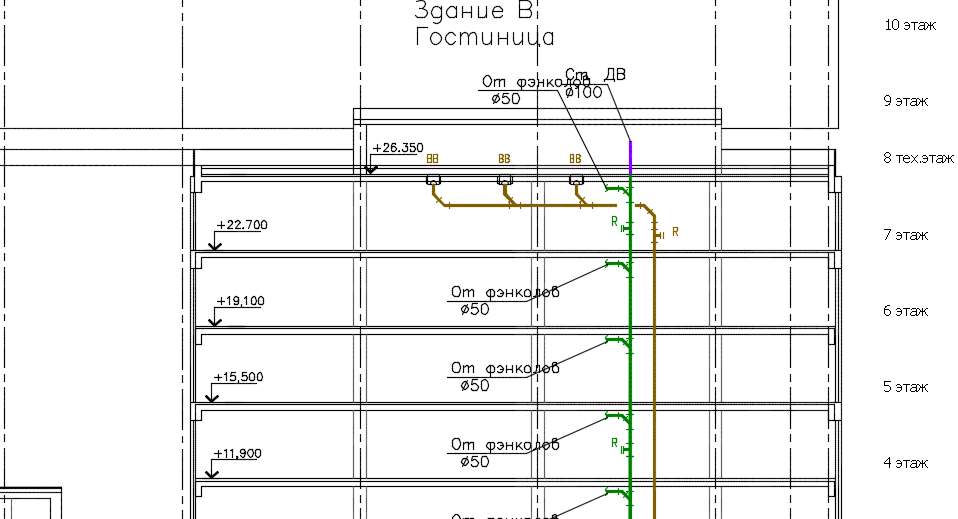
- E - network for sewage from the fan coils, from the HVAC equipment and random drains from the technical premises in the above-ground part of the complex;
- DN - pressure drainage sewer to remove water from the vents of the ventilating chambers and I&H;
- D1 - network of gravity drainage drainage system for water removal from the floor of the underground parking lot when the automatic firefighting system is triggered, etc;
- D1H - pressure drainage sewer to remove water from the pits (when the automatic firefighting system is triggered).
Household waste water (K1) from the office part of the complex, from the restaurant c/o and from non-residential premises is drained into the on-site network of domestic sewage. Household waste water from the hotel by a separate outlet is discharged into the on-site network of domestic sewage. Then domestic sewage is drained into the city's network with the connection to the collector DN300 domestic sewage passing on the street. according to the specifications for water supply and sanitation.
Industrial (fat-containing) wastewater (K3) is drained into the intrasite network of domestic sewage. Separate internal networks are provided for the catering company serving the restaurant in the building and the catering company serving the hotel restaurant and the canteen of the office center.
These networks are connected before the grease separator of the indoor unit. Then the treated wastewater from the catering enterprises is diverted by the sewage pumping station to the pressure outlet and enters the on-site network of domestic sewerage.
Conditionally clean water (networks K2, D1, D1n, Dn) is discharged into the on-site drainage system. Separate outlets of systems K2, D are provided for the hotel. Then, conditionally clean water is discharged into the city drainage system, according to the technical conditions for connection to the city system of surface water drainage. This project does not consider the intra-site sewage network. Domestic sewage networks are carried out to the branch from the riser, located in the "wet" area of the apartment and non-residential premises.
Drainage of domestic wastewater from the sanitary facilities located within the parking area is performed in full. Drainage networks for drainage of condensate from air conditioners are carried out to the branch from the riser to the apartment or non-residential premises. Drainage of conditionally clean water from the parking lot firefighting and drainage of "accidental" drains from the technical premises is carried out in full. Estimated costs of wastewater disposal systems are shown in tables 1,2,3.
Table 1. Estimated costs of sewage disposal systems of the entire hotel and office complex.
|
Name of the system |
Required head at the inlet |
calculated consumption |
Installed electric motor power |
Note Note |
|||
|
m3/day |
m3/hour |
l/s |
in case of fire, l/s |
||||
|
Household waste water K1 |
186,8 |
43,4 |
14,8 |
Including production can. |
|||
|
Drainage network K2 |
- |
- |
30 |
||||
|
Drainage network DN |
5 |
1,5 kW |
|||||
|
D1H drainage network |
10 |
2,6 kW |
|||||
Note. Domestic wastewater includes K3 flow from all catering enterprises located in the hotel and office complex, which will be: 140.0 m3/d, 33.5 m3/h; 11.7 l/s.
Table 2.
Calculated costs of sewage systems of the office part and the restaurant (Buildings).
|
Name of system |
Required head at inlet |
Estimated flow rate |
Installed electric motor power |
Note Note |
|||
|
m3/day |
m3/hour |
l/s |
in case of fire, l/s |
||||
|
Household waste water K1 |
167,2 |
39,8 |
13,6 |
Including production can. |
|||
|
Drainage network K2 |
- |
- |
23 |
||||
Note.
-
Domestic wastewater includes the consumption of industrial sewage K3 from the catering company located in the building "C", serving a restaurant on the 1st floor of the same building. Its flow rate will be: 26.1 m3/d, 7.6 m3/h; 4.7 l/s.
-
Included in the sanitary sewage is the K3 flow from the catering facility in Building "C" serving the restaurant on the 2nd floor of the hotel in Building "B" and the canteen of the office building on the 2nd floor of Building "A". Its flow rate will be: 113.9 m3/d; 29.0 m3/h; 10.3 l/s
Table 3: Estimated consumption of the drainage systems of the hotel.
|
Name of the system |
Required head |
Rated flow |
Installed electric motor power |
Note- Note |
|||
|
m3/day |
m3/hour |
l/s |
in case of fire, l/s |
||||
|
Household waste water K1 |
19,6 |
5,3 |
4,0 |
||||
|
Drainage network К2 |
- |
- |
7 |
||||
-
Justification of the adopted systems of collection and diversion of waste water, wastewater volume, concentrations of pollution, methods of pre-treatment, used reagents, equipment and instrumentation.
For sewage from sanitary devices of offices, restaurants and non-residential premises of the complex, a gravity network of domestic sewage (K1) is provided. A separate network of sanitary sewage is provided for draining the sanitary appliances of the residential and non-residential parts of the hotel.
From outlets, domestic wastewater is discharged into the intrasite network of domestic sewage. Wastewater from the sanitary units located below the level of outlets are discharged into the pressure network of domestic sewage K1H gravity domestic sewer network for non-residential premises.
Since the sanitary units from which domestic sewage is drained have a small number of units (3-4 pcs.), the compact pumping station SOLOLIFT2 from Grundfos is used as a unit for draining domestic sewage. For the sanitary sewage systems of the office part of the complex and the hotel there are separate ventilation parts.
The ventilation part is designed to ventilate the external networks of the sanitary sewer and to prevent the formation of vacuum in these networks. Domestic sewage of the office and hotel part of the complex has no specific impurities. No pretreatment is required before discharging them into the city's sanitary sewer system.
Industrial (grease-containing) wastewater, on separate networks for catering company serving a restaurant in the building " C C" building and the catering enterprise serving the hotel restaurant and the office center canteen, through separate networks are taken to the grease separator, indoor installation. The grease separator is designed for the total flow rate of all catering enterprises of the hotel and office complex. Parameters of the grease separator: brand and model ACO HydroJet - RAE The model is ACO HydroJet - RAE; nominal capacity - 15 l/s. The grease separator is equipped with an automatic flushing device, as well as a system for removing accumulated sludge and grease from it.
A pipe line for sludge and grease removal from the grease separator with installation of a quick coupling for connection of a sewage truck on the facade of the building is provided. For the production sewage system, there is a separate ventilation network for each catering facility. A separate ventilation network is also provided for the grease separator. After treatment in the grease separator, wastewater enters the reception tanks of the sewage pumping unit. Then the treated industrial waste water is discharged through the pressure outlet to the on-site domestic sewage system.
Selection of a pumping unit for pumping treated industrial waste water.
The required flow rate for the pumping unit is 11.7 l/s, equal to the maximum inflow of industrial wastewater, according to the calculation of flow rates.
Required head for the pumping unit:
Where:
H geom - geometric lift height. H geom = 5 ;
Δh network - head losses in the network, including local resistances. Δh network = 4 m;
H Hdp is the free head required at the pouring out of the pipeline. H свв=1 m;
We adopt the pumping station Grundfos MD 1.80.100.44.51D /450-2 SE ( Q =13.9 l/sec, H =12 м, P 1=2х4,9 kW). The pumping unit is equipped with two receiving tanks of 400 l each. The unit is provided with 2 pumps (1 working, 1 standby). The pumps operate alternately.
-
Justification of the adopted procedure of collection, utilization and disposal of waste - for industrial facilities.
As a result of the operation of the shops for pre-treatment of food products, bakery and restaurant, wastewater with high content, sludge and fatty products is formed. These contaminants are transported through the internal networks of the production sewer to the outlets of the grease separator. The process of grease separator cleaning is performed by specialized organizations using equipment that prevents the contact of contaminants with the external environment with further removal of waste to landfills.
-
Description and justification of the scheme of laying sewage pipelines, description of sections of laying pressure pipelines (if any), conditions of their laying, equipment, information about the material of pipelines and wells, methods of their protection from the aggressive effects of soil and groundwater
The laying of networks of domestic, industrial sewage and drainage to provide: openly - under the ceiling of the parking lot, technical premises, where possible laying in accordance with the standards; hidden - in communication shafts, in the space of the retaining ceiling of the premises of common use. The necessary number of revisions and cleanings are provided for the domestic sewer network. In the premises there shall be the installation of floor drains (where necessary) according to 30.13330.2012 SP. The manufacturer of drainage systems is HLAustria. Main networks and risers of gravity-flowing domestic and industrial sewage execute from cast-iron SML pipes.
Distribution within the sanitary units (where necessary) shall be made of noise-absorbing polypropylene pipes. Pressure network from the compact pumping units of polypropylene pressure pipes, reinforced according to TU 2248-023-41989945-2003. The laying of network K1n from the pumping unit MD 1.80.100.44.51 D /450-2 SE Provide for electric-welded steel pipes according to GOST 10704-91.
At the intersection of walls and floors, on the polypropylene pipe to provide installation of fire sleeves. The diameter of the pipelines to determine the calculation. The material of pipelines and wells of the outdoor network, as well as methods of protection against the aggressive effects of groundwater, see the section on outdoor networks. Installation and testing of gravity and pressure domestic sewerage network shall be carried out in accordance with the recommendations of the pipe manufacturer.
-
Solutions for stormwater drainage and calculated volume of rainwater runoff.
Rainwater and meltwater from the roof of each building of the complex through the gravity network of the rainwater drainage system are drained by gravity to the outlets. From the outlet, rain and melt water enters the on-site drainage network. Rainwater drainage network is installed with SML pipes with reinforced connectors, withstanding pressure up to 10 bar.
The routing of the drainage network shall be performed similarly to the routing of the domestic sewerage network. Provide the required number of revisions and cleanouts on the drainage network. The roofs are equipped with drainage gutters for operable and non-operable roofs with electric heating and protective gratings against debris HL brand made in Austria. The section of the network from the funnels to the riser is thermally insulated to prevent condensation.
Calculated flow rate of storm water for each of the roofs:
Restaurant roof
Operable roof at +10.330;
q20 - intensity of rain, l / s per 1 ha (for this terrain), duration of 20 min for the period of a single exceedance of the calculated intensity, equal to 1 year (taken according to SP 32.13330.2012) q20 = 80 l / s per ha.
q5- intensity of rain, l/s from 1 ha (for this terrain), duration of 5 min at the period of single exceeding of design intensity, equal to 1 year q5=214 l/s from ha
F1- total estimated drainage area from the roof with a slope greater than or equal to 1.5 FС=342.2 m2
F2- total estimated area of drainage from a pitched roof. FС=200 sq.m.
Hotel roof
The roof of the hotel consists of non-operated roofing at +25.050m and usable roofing at +22.650m.
Non-operated roof ;
q20- intensity of rainfall, l/s per 1 ha (for this terrain), with a duration of 20 minutes in a period of single exceedance of the calculated intensity, equal to 1 year (taken according to SP 32.13330.2012) q20=80 l/s per ha
F - the total calculated area of the watershed. FB = 870 sq.m.
The roof of the office building (building A)
The roof of the office building consists of non-operated roofing at +55,300m and operated roofing at +51,850m.
Rainfalls from the non-operated roof are discharged to the underlying operable roof by means of an external drainage system.
Utilized roof;
q20- intensity of rainfall, l/s per 1 ha (for this terrain), with a duration of 20 minutes in a period of single exceedance of the calculated intensity, equal to 1 year (taken according to SP 32.13330.2012) q20=80 l/s per ha
F - the total calculated area of the watershed. FA=2002 sq.m.
The total flow of storm water will be equal:
-
Drainage water collection and diversion solutions.
Drainage network of air conditioners and "occasional" drains from technical premises. Gravity (D) and pressure (DN).
Drainage water from the air conditioners of the hotel rooms as well as "random" and permanent drainage from the technical premises located in the building B are drained into the drainage network of the above-ground part of the building. These drains are conditionally clean and are discharged without pre-treatment into the on-site rainwater drainage network. Drainage water from air conditioners, which are located in non-residential premises of the building B, is discharged into the domestic sewage network.
These drains will be discharged with a jet break of at least 20 mm into a drip funnel with a "dry" siphon. Drainage water from air conditioners in offices, restaurants, as well as "occasional" and permanent drainage effluent from technical rooms located in the building A and C are discharged into the drainage network of the above-ground part of these buildings. These drains are conditionally clean and are discharged without pre-treatment into the on-site rainwater drainage network
Outdoor drainage from the -1 floor technical premises with the help of drainage gutters HL drainage water from the technical premises on the -1 floor by means of HL drains. Drainage effluents from the technical rooms on the -2nd floor are drained by gravity through the pipelines or through a slope into the pits installed directly in the technical rooms on the -2nd floor. Wastewater shall be removed from the sumps in the pressure mode, using drainage pumps AP 12.40.08.3 (1 pcs.) manufactured by Grundfos. The operation of the pump units is fully automated.
In each pit is located one pump with capacity of 1.5 l / s and a head of 12.8 m each. Water is pumped through the pressure drainage network to the internal drainage system of the building. No redundancy is provided for the drainage pumps that remove "accidental" drains. Main network, risers and downspouts of gravity drainage to be made of cast iron SML pipes. The pressure drainage network should be made of steel water and gas pipes according to GOST 3262-75. D network should include the necessary number of revisions and cleanings in accordance with 30.13330.2012. Laying and installation of the system to perform similarly to the network of domestic sewage.
Drainage network for the drainage of effluent when the APT system is triggered.
Gravity (D1) and pressure (D1H). Wastewater resulting from triggering the automatic fire suppression system and violation of waterproofing of the base plate is discharged into the network D1. Wastewater from the -1 floor is drained by means of drains of the company HL installed in diversion channels. There is a floor slope to the troughs.
Then the effluents are drained by gravity pipelines to the drainage pits on the -2nd floor. The effluents from the 2nd floor are discharged to the drainage troughs via the slope, from where the drainage water flows into the drainage pits. Drainage of sewage from the pits is performed in pressure mode with drainage pumps DP 10.65.26 (2 pcs.) by Grundfos.
The operation of pump units is fully automated. Two pumps (operating and reserve) with 11.3 l/s capacity and 12.5 m head each are located in each pit. The number of pumps and their redundancy shall be specified at the stage of DD. The pumps discharge water through the pressure drainage network via a separate pressure outlet into the external storm water drainage system.
The route of the pressurized