Design of the air-conditioning system in the Business Center
Refrigerating beams are gaining more and more popularity. Our project organization designed and installed the air-conditioning system in the Business Center for a visiting tenant, based not on fan coils, but on beams. In my opinion, a very dubious alternative to fan coils or central air conditioners. Better, of course, to divide. But nevertheless, we have fulfilled the system, we have balanced it and it cools the workers of the BC very successfully)
DESIGN AIR CONDITIONING
5. BASIC DESIGN AIR CONDITIONING SOLUTIONS.
5.1. To maintain the set temperatures in the office premises, where the temperature may rise during
the account of internal heat excess above that required for normal work of people and the installed in them
equipment provided air conditioning system in accordance with the specifications.
5.2. Cooling capacity of the designed air conditioning system does not exceed the maximum power
Qx = 60 kW at the connection point allocated to the unit of the rented area in accordance with the technical
conditions and technical characteristics of engineering systems of the building.
5.3. The cold source for the air conditioning system of the office premises is the existing ones.
cooling network of the building in accordance with the specifications. Pipeline Connection Point
the refrigeration center (design boundary) is located in axes 22-23 / В-Г.
5.4. Coolant of the cooling system for fan coil units - prepared water with parameters t ° = 16/19 ° С
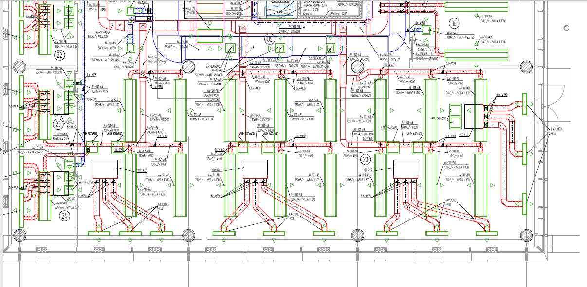
5.5. The air conditioning system is provided for all premises of the office, except for bathrooms, utility
premises and server rooms. For air conditioning of premises, 2-pipe fan coil units and
cassette type firms AERMEC, working on recirculated air in automatic mode, as well as
Flaktwood Wega II cooling ceiling beams. Fan coils and beams are equipped with air
filter, 3-way (and 2-way for beams) valve with 220V drive and wired wall control
controls for each fan coil. Fan coils installed hidden behind a false ceiling mounted on fan coil units
plenum boxes, ventilation plenum and exhaust grilles on a false ceiling. Supply and exhaust
lattices are equipped with static pressure chambers. Ceiling beams and cassette fan coil units are installed in
grid false ceiling.
5.6. Switching the fan coil on and off, room temperature and fan speed
controlled by a wall mounted wired remote control. Location of control panels
fan coils (with reference to the building envelope and installation height) look in the project of the brand AR.
5.7. Electrical connection of control panels to look at the project brand EOM.
5.8. Fan coils are selected to maintain the temperature at a low fan speed.
5.9. Pipelines of cooling systems for fan coils are laid hidden in the space of suspended
ceilings of steel water and gas pipes with the necessary hygienic certificates.
5.10. The pipes of the cooling systems of the fan coil are insulated with thermal insulation of foamed rubber
Type "K-flex ST", 9 mm thick according to the technology of K-flex.
5.11. Pipelines at the intersection of floors, interior walls and partitions are laid in sleeves
from non-combustible materials, the edges of the sleeves 40 mm protrude from the level of the surfaces of the walls, partitions,
ceilings, floors, but are on the same level of finishing (with finishing) surfaces of walls, partitions, ceilings,
floors
PROJECT DOCUMENTATION OF AIR CONDITIONING SYSTEM
5.12. The project provides for the required number of taps, transitions, tees.
5.13. At the point of connection to the pipelines of the refrigeration center located in the axes 22-23 / V-D recess from the riser
cold supply is made of steel water and gas pipes with a diameter of 80 mm. On the supply pipe
a mud filter Du80 is installed with a drain ball valve Du15, cut off by ball valves on both sides
Du80 The return pipe is equipped with a balancing valve DN80 and a ball valve DN80. Additionally
on the supply and return pipelines between the shut-off ball valves are installed control
measuring instruments (pressure gauges, thermometers).
5.14. On pipelines of cooling systems for fan coil units and chilled beams at the connection point of the fan coil unit
(chilled beam) a mud filter with a drain valve and a ball valve are installed on the supply pipe,
A return valve and a ball valve are provided on the return pipe. Rebar diameters
determined by the project of calculation.
5.15. Flush the pipelines of the cooling system before connecting the fan coil units.
5.16. Condensate drain from fan coil units and chilled beams is designed for utility pipes
sewage system through siphons for air conditioners HL136N by Hutterer & Lechner GmbH with water trap and
mechanical odor-blocking device that prevents odor from being drained when water is drying in
water trap, with wiper-wiper, with rotatable horizontal outlet.
5.17. The drainage system is laid self-flowing of polypropylene pipes type PRO AQUA STABI PPR /
AL / PP-R 32x6 mm SDR 5 PN 25 HOT WATER, in accordance with specifications, having the necessary
hygienic certificates in the space of the suspended ceiling with a slope of at least 0.01 in the direction of the drip
funnels. To clean the drainage system all turns are provided with T-shaped with removable plugs. In
avoiding the formation of condensate drainage pipes are insulated with foam rubber type "K-flex
ST ", 6 mm thick according to K-flex technology.
5.18. The project of the brand EOM provides for the shutdown of air conditioning systems in case of fire.
5.19. To ensure the maintenance and repair of air conditioning components laid in
the space behind the suspended ceilings, in mines and ducts, the project of the AR provides access to them through
doors, niches, hatches.
6. MAIN DESIGN DECISIONS ON AIR CONDITIONING OF A SERVER ROOM.
6.1. Cooling server provided around the clock in 24/7/365.
6.2. The server air conditioning system is made according to the (N + 1) scheme with cooling of the room
server at rated load with one conditioner, with alternating operation (for uniform wear) and
connecting two air conditioners in peak loads.
6.3. The estimated temperature in the server is taken to be +20 ° C, the tolerance is from 18 to 24 ° C when measuring
at a height of 1.5 meters above the floor. Humidity is not monitored.
6.4. Place the outdoor units of the server air-conditioning system on the 1st underground floor of the building in axes 21 / B
on metal brackets mounted on the wall in accordance with the plan. Actual placement
determine during installation and reflect in the as-built documentation.
6.5. Indoor units are applied wall-mounted company Mitsubishi Electric MS-GF60VA, outdoor units
working only on the cold.
6.6. The piping of the air conditioning system of the server room is laid out of copper pipes inside the server room.
rooms are open on the ceiling and outside the server room behind suspended ceilings with fastening to
overlap. Pipelines on the 1st underground floor should be laid in a metal tray.
6.7. The piping of the air conditioning system of the server shall be insulated with foam rubber insulation.
"K-flex ST", 6 mm thick according to K-flex technology.
6.8. To ensure the operation of the air conditioning system in the cold period, equip the outdoor units
low temperature kits.
6.9. Condensate drainage is provided for the projected drainage system of the office part. Condensate lift
from indoor units to piping drainage system is carried out with the help of drainage pumps company
Sauermann, embedded in air conditioning.