Design of firefighting automatics for office in business center
Completed the engineering design and installation site for PPA, SPA (firefighting, fire automatics systems). The construction and installation works were carried out on the basis of working documentation developed by us for the tenant's office in the Business Center (BC) building.

DESIGN OF PPA FIRE-PREVENTIONAL AUTOMATION
3.1. The fire automatics system (hereinafter SPA) is designed in accordance with the requirements of
the territory of the Russian Federation of norms and rules of design, project of fire prevention measures and special technical
conditions (STU) on the design of fire protection.
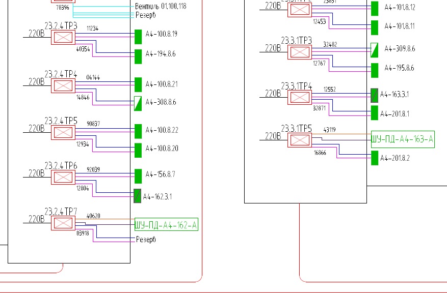
3.2. The facility provides for a new SPA shield ShchUP-23-1 / A4-2-NSV with connection to the existing cable
The SPA of the ShP23.3.1 building in the ShchUP-23-1 / A4-2 switchboard installed on the 1st floor in the room A4-100-509 in accordance with
technical conditions. Central SPA equipment (central panel, uninterruptible power supply and
etc.) existing, fully assembled and commissioned and in this project is not considered.
3.3. The designed spa is designed to manage the office engineering systems.
3.4. The projected SPA, by signal from the automatic fire alarm system, controls the closure
fire-retarding valves (OZK) and dampers, opening the valves for smoke removal and air overpressure (KDU),
unlocks doors equipped with an access control system, disables ventilation systems and
conditioning.
3.5. To control the valves OZK pre-installation of two transponders 808600.230 with 2 modules
IQ8FCT804981 each. For control of the ACS and OV systems, the installation of two 808623 transponders is foreseen.
Transponder connections use the existing esserbus® / esserbus®Plus ARK23 loopback module.
3.6. Algorithm of work of SPA for the A104-1 room:
- Turn off the supply and exhaust installation A4-101-AB. (existing SPA)
- Switching off exhaust systems B1, B2, server air conditioning systems, fan coil units and climate beams
projected office (projected spa)
- Closing OZK A4-101.8.11, A4-101.8.12 by applying a signal to the OZK. (existing SPA)
- Closing OZK A4-NSV-101-01, A4-NSV-101-02, A4-NSV-101-03, A4-NSV-101-04 by giving a signal to
OZK. (projected spa)
- Inform the engineering systems on the state of the valves OZK. (existing SPA)
- Inform the engineering systems on the state of the valves OZK. (projected spa)
- To open the valves PD and remote control (smoke) and control the state by giving a signal to
PD and remote valves. (existing SPA)
- To ensure the smoke on the floor of ignition, in the space of offices. Why enable and provide
control of the state of the fans of the remote control by sending a signal to the complete cabinets of the ShA-PD system of the PA.AE system.
(existing SPA)
- Provide air supply on the floor of fire, in the space of offices. Why enable and provide
control of the condition of the PD fans by sending a signal to the complete cabinets of the ShA-PD system of the PA.AE system.
(existing SPA).
PROJECT DOCUMENTATION
4. POWER SUPPLY AND GROUNDING
4.1. In accordance with the EMP, the security and fire alarm and alarm systems are installed to ensure
reliability of power supply are assigned to consumers of the 1st category.
4.2. Power supply and grounding for a fire automatics system with an alternating current of 220V according to the 1st category
Electrical installation code and grounding (zeroing) are provided by the Customer.
5. INFORMATION ABOUT THE ORGANIZATION OF MANUFACTURING AND MANAGEMENT OF ASSEMBLY WORKS
5.1. Installation of electrical wiring and hardware of the fire automatics system shall be carried out in accordance with
with РД78.145-93 (Manual to РД, a part 2), and also with observance of actions for safety measures and safety
labor.
5.2. Connections and taps of wires and cables should be made in switching boxes in the way
soldering or using screws.
5.3. Zapotolochnaya and open wiring should be in the PVC pipe with metal fastening
staples to overlap.
5.4. Joint laying of SPA loops with lines of 110 V or more in one box is not allowed,
pipe, harness, closed channel of building construction or on one tray. Joint laying
These lines are allowed in different compartments of boxes and trays with continuous longitudinal partitions with
fire resistance of 0.25 h from non-combustible material.
5.5. Cutting cables to make after control promera laying routes with regard to the location
projected equipment.
5.6. Clearances at pipe penetration points through building structures should be sealed with fireproof ones.
materials.
5.7. Installation work should be carried out taking into account the actual location of engineering communications.
5.8. Before installation, check the integrity and operability of the equipment, and
prepare materials, components and tools.
5.9. The condition of cables and wires before installation is checked by an external examination. In addition to inspection
the cable is routed and the integrity of the core insulation is checked.
5.10. To eliminate interference from the electrical network, laying low-voltage lines is performed at a distance
not less than 0.5 m from power circuits and lamps.
5.11. The distance from the cables and insulated wires of the warning system, laid open,
directly on the elements of building structures of the premises to open storage (placement)
