
Design of an individual heat supply station in a residential complex
Our project company completed the working documentation of the central heating point of the central heating unit in the residential complex with underground parking.
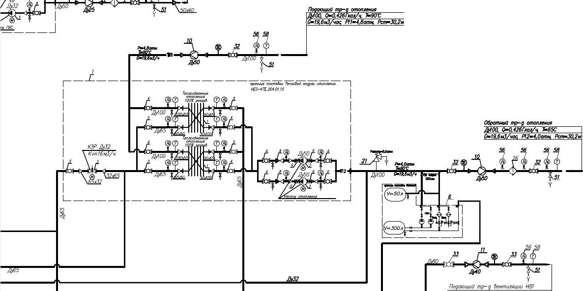
Designing Heating point
The calculation of the equipment of the central heating station should be performed at the maximum heat load at the outdoor temperature: -25 ° C.
- Leave the connection point of the central heating station unchanged - the outside of the camera
- The parameters of the CTP to accept according to the regime map.
The temperature graph in the heating period, adopted by the qualitatively quantitative method in accordance with the temperature of the outside air at the heat input 150-70 ° C. To calculate the heat networks and equipment of the heat point in the winter maximum mode, take the cut in the heat pipeline supply network of 130 ° C at an outdoor temperature of -17 ° C. For the calculation of heat networks and equipment of a heat point during the transition period, take a cut in the flow pipe of the heating network of 77 ° C at an outdoor air temperature of + 2.6 ° C. The temperature schedule at the heat input in the summer period is 77-40 ° С with a stop for carrying out scheduled preventive maintenance.
5. Perform work on disabling the demolished building at: 1st
6. Perform a calibration calculation with the determination of the throughput capacity of the thermal input of the central heating point, offsetting the reduction of the thermal load. If necessary, develop a project and shift the heat network to the calculated diameter.
7. If necessary, develop a project and perform a reconstruction of the heat chamber with the installation of valves “ball valve” type.
- Develop and implement measures to ensure uninterrupted heat, water supply to all existing consumers.
- When rearranging thermal input, the project should be carried out in accordance with the requirements of SP 124.13330.2012 (updated edition of SNiP 41-02-2003), SP 41-105-2002, taking into account the use of steel pipes and fittings, insulated with polyurethane foam in a protective sheath of polyethylene made in the factory but GOST 30732-2006 with a system of operational remote monitoring of the state of thermal insulation and the use of valves of the type "ball valve".
- When developing the project for the reconstruction of the central heating point, follow SP 124.13330.2012 (updated edition of SNiP 41-02-2003), SP 41-101-95, SaiPiN 2.1.4.24.96-0.9, Resolution of the Government of the Russian Federation No. 87 dated February 16, 2008 sections of project documentation and requirements for their content ”, Order of the State Construction Committee of Russia dated December 13, 2000 No. 285 on“ Approval of the Model Instruction for the Technical Operation of Heating Networks of Municipal Heat Supply ”. As part of the automated control system, it is recommended to be guided by the “Standard technical specifications for the automated process control system of the central heat points (APCS TSTP)” approved on 05.05.2012.
- The project should include a calculation of the heating surfaces of water heaters for each system with an indication of the required heating surface with a margin of 10%, checking the availability of supply water supply in the amount of 15%, taking into account ensuring the hot water temperature in the places of water discharge is not lower than 60 ° C .
- In the project, provision should be made for installation of automation equipment at the heat input to ensure the specified pressure in the return pipeline, as well as protection devices for equipment, heating networks and heat consumption systems against unacceptable pressure changes and water hammering in accordance with GOST R 54086-2010.
- If necessary, design and perform the replacement of the heat energy metering unit in the central heating station:
issued by the Branch number 11 "Gorenergosbyt" PJSC "MOEK".
10.4. Provide an emergency jumper after head gate valves, stop valves after an emergency jumper on the direct and return pipe of the heating network and a lowering pipe (with a diameter calculated in accordance with the heat load on the heating), after the backup valve on the return pipe.
11. Power supply and Electrical equipment:
11.1. In order to increase the electric power, obtain permission to connect additional electric power of the central heating station to the grids of PJSC MOESK:
draw up an act of technological connection
11.2. To be guided by the requirements of the "Rules for electrical installations" (ПУЭ).
11.3. The reliability category of the power supply for an accident is determined in accordance with SP 4] -101-95 and SP 31-1 10-2003.
11.4. Electrical networks should provide the ability to work welding machines and hand electromechanical tools.
11.5. Local control of valves with electric drives and pumps should be duplicated by remote control from a switchboard located at a height not lower than the planning level of the ground.
11.6. Provide a soft start installation of fire extinguishing pumps.
11.7. Provide installation of variable frequency drives (VFD) on the cold-water pumps.
12. When placing equipment (pumps) of the cold water supply and fire fighting outside the premises of the central heating station, it is necessary to:
perform design in accordance with the specifications of JSC "Mosvodokanal";
provide for a separate electrical input accounting, electrical cabinets and automation;
transfer this equipment to the specialized organization of Mosvodokanal JSC.
13. When designing the reconstruction of heat supply facilities, it is necessary to carry out measuring drawings of buildings to be reconstructed and obtain an engineering conclusion from a specialized organization on the bearing capacity of foundations, the condition of the bearing and enclosing structures, and, if necessary, provide a roof over the entrance to the central heating station.
14. The recommended list of materials and equipment for installation in the central heating point: pipes according to GOST 8731-74, GOST 8733-78 steel 20 seamless, hot-deformed, heat-treated group B;
water heaters - plate APV "Teploteks", Alfa-Laval, "Danfoss", "Ridan", "RoSVEP";
pumping equipment - Grunfos, Linas, WILO with frequency-controlled converters Mitsubishi Electric, Danfoss, Schneider Electric, ABB, Vacon and stations of group control of pump units;
on the primary coolant inlet, the pressure differential controller “Samson”,
Danfoss;
fittings - on the pipelines input to the “ball valve” heat point of the manufacturers Klinger, Ronex, Vgoep, Danfoss (type JP), install no more than 2 meters from the wall, not more than 1.5 meters from the floor. As the rest of the shut-off valves for mains water - ball valves of the brand “Vgoep”, “Vexve”, “Sital”; hot and cold water - ball valves "Vgoep";
membrane expansion tanks of the pressure maintenance installation “Reflex”, “Variomat”, “Flamco” and other similar manufacturers, in the heat substation room, control from the controller;
automation system: control device “Sauter”, “Transformer ML”, MFK-1500 (GC “Tekon”), mobile communication unit, “Delta M” hard disk meter with dispatching output;
actuators of the KZR brand or 25ch945p of the KT1, KT2, ST01, MRP10 brands or Danfoss, Broyen-Koryus firms.
15. If necessary, develop a project and perform work on the reconstruction of internal systems of heat consumption of buildings in accordance with joint venture 30.13330.2012 (updated edition of SNiP 2.04.01-85 *), joint venture 60.13330.2012 (updated edition of SNiP 41-01-2003), joint venture 118 actualization
15.1. Working pressure must be accepted: in heating systems with cast iron radiators - not in heating systems with steel convectors -
15.2 In the project to provide for the connection of the heating system according to an independent scheme. Link the hydraulic resistance of the heating system to the given static and working heads of the heat network at the connection point.
15.3. Provide for the connection of the ventilation system of the facility according to an independent scheme.
15.4. In the project to provide for the connection of the hot water supply system of the object in accordance with SP 41-101-95.
15.5. Heating units, ventilation units and hot water supply points for each circuit should be equipped with auto regulators, control and metering devices in accordance with the “Rules for heat energy and heat carrier metering”, applicable to the S & P.
15.6. Exclude the placement of elements of the internal systems of the building (heating pipes, hot water supply, cold water supply, sewage, etc.) in the central heating point.
16. The customer must:
16.1. Prior to the development of working documentation, agree on the direction of the heat network in PJSC MOEK.
16.2. Develop project documentation and transfer 2 copies. on paper for consideration by PJSC MOEK (t. (495) 587-77-88).
16.3. The agreement is made when submitting 1 copy. heat network project, central heating point (heat mechanical part), internal heat consumption systems in electronic form in PDF format.
16.4. To carry out construction control (technical supervision) on its own or with the involvement of persons authorized to carry out this type of work on the basis of the contract.
16.5. All work performed must be reflected on the executive drawings, confirmed by the operational Branch, the customer and the contracting organization. Executive drawings are transmitted to PJSC MOEK (t. (495) 587-77-88).
16.6. Prior to the start of the coolant supply:
call an official of the Moscow MTU of Rostekhnadzor to inspect the constructed heat consuming installations;
obtain a permit for commissioning in the Moscow MTU of Rostekhnadzor, in accordance with 42 of the “Rules for connection to heating systems” and p. 2.4.2., 2.4.8., 2.4.11 "Rules for the Technical Operation of Thermal Power Plants".
After coolant supply:
conduct a comprehensive 72-hour testing of the equipment of the central heating station for a nominal heat load, in accordance with pp 2.4.9. "Rules of technical operation of thermal power plants" and submit to the operational branch of all systems in working condition.
17. To draw up an energy supply contract with Branch No. 11 “Gorenergosbyt”
PJSC "MOEK" (t. (495) 587-97-11).
The relative mark of the floor of the central heating point is 6.9 m.
The absolute mark of the floor of the central heating point is -129.3 m.
The height of the central heating point is 3.60 m.
The area of the central transit point is 66.9 m.
The CTP is located along the axes - "2.A - 2.G", "2.11 - 2.12"
Calculated parameters of CTP-2
Heating system (independent) 90-65 С °
Provide for the central transit point:
- pump equipment Grundfoss;
- a two-line heat metering unit VIS.T on the input of the TSC should be able to transfer data to the control room, the project should be carried out in a separate album;
- for systems of heating, ventilation, broad tanks "Reflex";
- regulation of coolant supply on the basis of automation and control valves manufactured by Danfoss / Freze, Danfoss stop valves ;
- plate heat exchange equipment ALFA LAVAL;
- thermal insulation made of foamed synthetic rubber K-FLEX;
- 100% redundancy in pumping equipment;
- 100% reservation of heat exchangers for each system, except for DHW;
- 100% reservation of hot water supply (electr. Boiler room) for the period of maintenance work on the vehicle;
- 15% reserve of heat load (Gcal / hour) for each system when selecting equipment for central heating stations and pipelines;
- provision of the local automation system of the control and monitoring center with the possibility of monitoring on the basis of Siemens equipment with data transmission to the complex CPU.
- heat meter equipment must have the function of data transmission to the BMS system;
- inside the cabinet marking of elements and conductors in accordance with the EMP and the requirements of the Customer.
- protective grounding (vanishing) of electrical equipment, in accordance with relevant rules and regulations.
- blocking of all elements of technological equipment in a safe state (in case of accidents, the threat of freezing of heaters, etc.).
- soft start and thermal protection of electric systems, if required by the corresponding specifications on the equipment used.
- thermal protection of electric motors (by built-in sensor, if available).
- equipping the systems with local indicating devices and electronic devices (in the section “TEPLOMECHANICS”);
- automatic activation of the backup pump when the working pump fails;
- for all engineering systems control / condition management:
Management (start / stop);
State (on / off);
Alarm "malfunction";
Monitoring the current status of control valves.
- control, protection, alarm and indication of malfunctioning of the circulation pumps of hot water supply, heating and ventilation, make-up and other equipment;
- water temperature control on the systems of hot water supply, heating and ventilation;
- regulation of pressure drop in the network pipeline;
local control of temperature and pressure in pipelines;
- control of temperature and water pressure at the input (output) of the heating system, on the supply and return pipelines of local systems (heating, ventilation, etc.);
- control of circulating pumps of hot water supply systems, heating supply of ventilation and heating with the help of a frequency electric drive, which changes the capacity of pumps depending on water consumption (the need to install frequency converters is defined in the section "TEPLOMECHANICS");
- maintaining the desired temperature in the hot water system;
- maintaining the set temperature in the heating system depending on the outdoor temperature and with the correction of the return heat carrier temperature;
- maintaining a predetermined pressure difference between the supply and return pipelines at the input unit to the substation and at the coolant supply to the ventilation systems;
- maintaining the desired temperature in the ventilation system;
- protection of pumps from the "dry run";
- Autostart of the pump on duty after the restoration of the short-term power supply.
GENERAL DATA OF THE PROJECT CTP
The present draft of the Central Heating Station No. 2 (hereinafter TsTP-2), located at the address: Moscow, is made in accordance with the current building codes and regulations on the basis of:
- Terms of Reference No. T-TZ3-03- issued by MOEK PJSC;
- Terms of Reference for the development of working documentation for a residential complex with an underground parking lot, reconstruction of office buildings with changes in the functional changes for housing.
The design used the following regulatory documents:
- SP 124.13330.2012 "Heat networks";
- SP 41-101-95 "Design of heat points";
- "Rules of operation of heat consuming installations and heat networks";
- "Rules for heat energy and coolant";
- "Technical rules for the design, construction and commissioning of water distribution thermal networks and subscriber inputs in Moscow";
- SP 61.13330.2012 "Thermal insulation of equipment and pipelines";
- SNiP 11-01-2003 "Instructions on the procedure for the development, coordination, approval and composition of project documentation for the construction of enterprises, buildings and structures."
- GOST 21.602-2003 "Rules for the execution of working documentation of heating,
ventilation and air conditioning. "
- GOST 21.205-93 "Legend of elements of sanitary systems".
- GOST R 21.1101-2009 “System of project documentation for construction. Basic requirements for design and working documentation ".
TECHNICAL CHARACTERISTICS OF THE PROJECT OF THE CENTRAL HEAT POINT №2
CTP-2 is located in the basement of the building on the -1 floor at -6.90 (129,300 m).
The area of the room is 66.9 m.
The upper heater is located at +23.30 m.
The thermal input of TsTP-2 is powered from the thermal chamber of the 1809/3 thermal network.
Heads at the point of connection taken:
- in the supply pipeline - 8.0-6.0 atm;
- in the return pipeline - 4.0-2.0 atm.
Calculated temperature graph of the heat network:
- Winter period at the inlet / outlet of the heat point (T1 / T2) -150 ° С / 70 ° С;
- The summer period at the entrance / exit of the heat point (T1 / T2) is 700С / 400С.
Selection of equipment is made according to the actual temperature regime: 130-70 ° С, taking into account the maximum possible temperature - 150 ° С.
Estimated temperature schedule of local systems:
- in the heating pipeline - 90/65 ° C;
- in the pipeline of ventilation - 95/70 ° C;
- in the GVS pipeline - 65/5 ° C;
According to the technical specifications of the Customer, the heat loads are: (see table).
water temperature in the return pipe of the heat network, ° C.
The diameter of the pipeline adopted Dn76h4,0 mm. The pipeline at this flow has the following indicators: V = 0.66 m / s, Ah = 10.5 kgf / m2m.
Consumption of network water: for ventilation, (coolant with parameters 130-70 ° С).
GbeKT = Ovent * 1000 * 1.15 / (T1-T2) = 0.3454 * 1000 * 1.15 / (130-70) = 6.62 m3 / hour;
Where QGVS is the maximum heat flow for ventilation, Gcal / h
1.15 - the safety factor;
p1 - water temperature in the supply pipe of the heating network, ° С; t2 - water temperature in the return pipe of the heat network, ° С.
The diameter of the pipeline adopted Dn76h4,0 mm. The pipeline at this flow has the following characteristics: V = 0.53 m / s, Ah = 6.7 kgf / m2m.
Consumption of network water: for hot water supply (coolant with parameters 70–40 ° С).
Gpbc = Qpbc * 1.15 * 18.2 = 0.3 * 1.15 * 18.2 = 6.28 m3 / hour;
Where Qgvs - the maximum heat flux on the hot water supply, Gcal / h
1.15 - the safety factor.
The diameter of the pipeline adopted Dn76h4,0 mm. The pipeline with this consumption has the following indicators: V = 0.5 m / s, Ah = 5.94 kgf / m2m.
Consumption of network water at the heating network input:
GceT = GOT + GBeHT + GrBC = 8.16 + 6.62+ 6.28 = 21.06 m3 / hour
The diameter of the pipeline of the heating system is taken equal to Dn108h4,5mm. The pipeline at this flow has the following indicators: V = 0.78 m / s, Ah = 8.9 kgf / m2m.
CALCULATION OF SECONDARY ITP SYSTEMS
CALCULATION OF THE HEATING SYSTEM
Secondary water consumption: for heating (coolant with parameters 90-65 ° С).
Gcx = Oot * 1.15 / (t1-t2) = 0.426 * 1.15 * 1000 / (90-65) = 19.60 m3 / hour;
Where 0ot is the maximum heat flow to heating, Gcal / h
- - safety factor;
t11 - water temperature in the heating supply pipe, ° С; t21 - water temperature in the heating return pipe, ° С.
The diameter of the pipeline adopted Dn108h4,5 mm. The pipeline at this flow has the following characteristics: Y = 0.74 m / s, Ah = 8.08 kgf / m2m.
Heat exchanger:
The calculations of the heat exchanger were made by experts of Alfa Laval Potok.
For the heating system, there are two heat exchangers connected in parallel, each designed for 100% heat load (1-standby; 1-working), the company Alfa Laval Potok, model T5-BFG. Power reserve: 15%; Surface margin: 9.7%; The surface area of the heat exchanger: 6.8m2, the number of plates - 78 pcs., Permissible pressure: 16 bar. Threaded connection DN50. The specification is provided in the project, Appendix No. 1.
Heating pump:
The calculations of the heat exchanger are made in the program " Grundfos Product Center".
The required flow rate of the transfer fluid (water 65 ° С) is 19.6 m3 / hour.
Losses in the circuit of the heat exchanger and piping of the thermal unit - 3.0 m. In.
Losses in the heating system - 8.0 m.st.st.
Choose pumps from Grundfos with remote frequency converters model TP 50-140 / 4 AFA-BAQE. Reserves reserve: 15%; reserve for head: 2 m; number of pumps - 2 pcs. (1-backup; 1-work). Operating point: Consumption is 20.6 m3 / h, Pressure is 13.86
m.st. Power 1,5 kW. Allowable pressure: 16 bar. Pipe connection: DN50.
Characteristics provided in the project, Appendix №2.
Shut-off control valve:
it ^ from max, 3 /.
Kv ~ / dr — m / h;
Gommax = 8.16m3 / h;
DR = 0.5 ATM;
Kv = 11.54 m3 / h;
Where: 0.5 atm - pressure drop across the valve with a fully open stem.
We select KZN flange VFM2 of Danfoss company Dv32 mm, Kvs = 16 m3 / h with electric drive ARE 152.
Calculation of valve KZR on cavitation:
APv max = Z (P ' - P us)> DR KZR;
where APv max is the maximum allowable cavitation free pressure drop across the valve;
Z is the cavitation coefficient;
P 'is the absolute pressure at the inlet of the valve (add 1 atm to the overpressure);
Рнас - absolute saturation pressure of water vapor at operating temperature;
APv is the pressure loss at the valve.
DKzr = 0.5 ATM.
Z - the coefficient of the onset of cavitation> 0.5 for the valve VFM2, Kvs = 16m3 / h, DN32 mm. If AFv max > DRcr, then the condition for cavitation free operation of the KZR is fulfilled.
P '= 6.0 atm (sm.TU) + 1 atm = 7.0 atm;
P us = 2.7 ATM, at t = 130 ° C;
DR v max = 0.5 (7.0 - 2.7) = 2.15 atm;
DR v max > DRKZR;
The condition for the non-cavitation work of the TFR is fulfilled.
Solenoid valve calculation:
Where: 0.3 atm - pressure drop across the valve with a fully open stem.
Select the solenoid valve of the company Danfoss, EV220B, Kvs = 4 m3 / h, DN15 mm.
AUPD heating systems:
Calculations of the automatic installation of pressure maintenance performed by the company "Reflex".
System volume (liters):
C = Qot * 13 * 1163 = 1.074 * 13 * 1163 = 16238 l. We choose the automatic installation for maintaining pressure:
The control unit AUPD: Reflex Variomat VS 2-2 The main tank AUPD: VG 300, 1 pc.
Damping tank: NG50, 1 pc.
Appendix №3.
CALCULATION OF VENTILATION SYSTEM
Secondary water consumption: for ventilation (coolant with parameters 95-70 ° С).
Ovent2 = Ovent * 1.15 / (t1-t2) = 0.3454 * 1.15 * 1000 / (95-70) = 15.89 m3 / hour;
Where Qvent is the maximum heat flow for ventilation, Gcal / h
- - safety factor;
t3 - water temperature in the supply pipe, ° С; thw - water temperature in the ventilation pipe, ° С.
The diameter of the pipeline adopted Dn108h4,5 mm. The pipeline at this flow has the following indicators: V = 0.59 m / s, Db = 5.17 kgf / m2m.
Ventilation heat exchanger:
The calculations of the heat exchanger were made by experts of Alfa Laval Potok.
For the ventilation system, there are two heat exchangers connected in parallel, designed for 100% heat load each (1-standby; 1-working), by Alfa Laval Potok OJSC, model T5-BFG. Power reserve: 15%; Surface margin: 12.6%; The surface area of the heat exchanger: 5.3 m2, the number of plates - 62 pcs. Permissible
pressure: 16 bar. Threaded connection DN50. The specification is provided in the project, Appendix No. 4.
Ventilation pump:
The calculations of the heat exchanger are made in the program " Grundfos Product Center".
The required flow rate of the transfer fluid (water 70 ° С) is 15.89 m3 / hour.
Losses in the circuit of the heat exchanger and piping of the thermal unit - 3.0 m. In.
Losses in the ventilation system - 9.0 m.st.st.
Select pumps from Grundfos with remote frequency converters, model TP 50-140 / 4 AF-А-BAQE. Reserves reserve: 15%; reserve for head: 2 m; number of pumps - 2 pcs. (1-backup; 1-work). Operating point: Consumption is 16.2 m3 / h, Head is 14.59 m.st. Power 1,5 kW. Allowable pressure: 16 bar. Pipe connection: DN50.
Characteristics provided in the project, Appendix No. 5.
Valve shut-off and control ventilation:
hl from max, 3 /.
V ~ / DR;
V pg clap
Gommax = 6.62m3 / h ;
DR = 0.5 ATM;
Ku = 9.36 m3 / h;
Where: 0.5 atm - pressure drop across the valve with a fully open stem.
We choose KZR flange VFM2 of Danfoss company Ду25 mm, Kvs = 10 m3 / h with electric drive ARE 153.
Calculation of valve KZR on cavitation:
DRU max = Z (P ' - P us)> DR KZR;
where DRU max is the maximum allowable cavitation free pressure drop across the valve;
Z is the cavitation coefficient;
P 'is the absolute pressure at the inlet of the valve (add 1 atm to the overpressure);
Рнас - absolute saturation pressure of water vapor at operating temperature;
DRU - pressure loss at the valve.
DKzr = 0.5 ATM.
Z - the coefficient of the onset of cavitation> 0.5 for the valve VFM2, Kvs = 10 m3 / h, Du25 mm. If ДРу max > ДРкзр, then the condition for cavitational operation of the KZR is fulfilled.
P '= 6.0 atm (sm.TU) + 1 atm = 7.0 atm;
P us = 2.7 ATM, at t = 130 ° C;
DR v max = 0.5 (7.0 - 2.7) = 2.15 atm;
DR v max > DRKZR;
The condition for the non-cavitation work of the TFR is fulfilled.
Solenoid valve calculation:
Kv =, G m3 / h;
^^ Rklap
G = Vsist * 0.2 m3 / h;
Vsist = 0.3454 * 11 * 1.163 = 4.42 m3;
G = 4.42 * 0.2 = 0.88 m3 / h;
DR = 0.3 ATM;
Rv = 1.61 m3 / h;
Where: 0.3 atm - pressure drop across the valve with a fully open stem.
Select the solenoid valve of the company Danfoss, EV220B, ^ 8 = 4m3 / h, Du15 mm.
Expansion tank of the ventilation system:
Calculations of the expansion tank are made by the specialists of the company "Reflex".
System volume (liters):
C = Owent * 11 * 1163 = 0.3454 * 11 * 1163 = 4419 l Select the expansion tank: G 500, 1 pc.
Section 3.3
CALCULATION OF THE GVS SYSTEM
Select the scheme of accession of hot water supply:
In accordance with paragraph 3.14 of SP 41-101-95 "Design of heat points", if this relationship is met:
Secondary water consumption: for hot water supply (heat carrier with parameters 65 ° С).
GrBC = Ogvs * 1.15 / (t1-t2) = 0.3 * 1.15 * 1000 / (65-5) = 5.75 m3 / hour;
Where QrBC is the maximum heat flow to the DHW, Gcal / h
- - safety factor;
g3 - water temperature in the supply pipe for hot water supply, ° С;
Тхе - water temperature in the cold water pipeline, ° С.
The diameter of the pipeline adopted Dn76h4,0 mm. The pipeline at this flow has the following characteristics: V = 0.45 m / s, Ah = 4.87 kgf / m2m.
Water consumption in the circulation pipe of the DHW system:
Stsirk = GrBC * 0.4 = 5.75 * 0.4 = 2.30 m3 / h.
The diameter of the circulation pipeline is taken Dn57x4.0mm. The pipeline at this flow rate has the following indicators: V = 0.33 m / s, Ah = 3.69 kgf / m2m.
DHW heat exchanger:
We divide the heat exchangers according to the load, in relation to the maximum - 60/40, where 60% of the maximum power is the 1st stage, 40% of the maximum power is the 2nd stage.
The calculations of the heat exchanger were made by experts of Alfa Laval Potok.
1st stage heat exchanger: T5-BFG, Alfa Laval Potok OJSC. Power reserve: 15%; Surface margin: 11.0%; The surface area of the heat exchanger: 5.8 m2, the number of plates - 67 pcs., Permissible pressure: 16 bar. Threaded connection DN50. The specification is provided in the project, Appendix No. 6.
2nd stage heat exchanger: TL3-BFG, Alfa Laval Potok OJSC. Power reserve: 15%; Surface margin: 10.0%; The surface area of the heat exchanger: 5.6 m2, the number of plates - 77 pcs., Permissible pressure: 16 bar. Threaded connection DN32. The specification is provided in the project, Appendix No. 7.
DHW pumps:
The calculations of the heat exchanger are made in the program "Grundfos Product Center".
The required flow rate of the transfer fluid (water 50 ° С) is 2.3 m3 / hour.
Losses in the circuit of the heat exchanger and piping of the block heat supply station - 5 m.st.st.
Losses in the system of hot water supply - 6.6 m.v.st.
Choose pumps from Grundfos without frequency converters, model CR 3-3 A-FGJ-AE-HQQE. Reserves reserve: 15%; reserve for head: 2 m; number of pumps - 2 pcs. (1- reserve; 1-worker). Operating point: Flow rate is 2.5 m3 / h, Head is 16.18 m.st.st. Power 0,37 kW. Allowable pressure: 25 bar. Pipe connection: DN32. Characteristics provided in the project, Appendix №8.
Valve shut-off and control DHW:
Ch Gbc max, 3 /.
Kv ~ / dr — m / h;
V ^ gklap
Ghvsmax = 6.28m / h;
DR = 0.5 ATM;
Kv = 8.88m3 / h;
Where: 0.5 atm - pressure drop across the valve with a fully open stem.
We choose KZR flange VFM2 of Danfoss company Ду25 mm, Kvs = 10 m3 / h with electric drive ARE 153.
Calculation of valve KZR on cavitation:
APv max = Z (P ' - P us) > DR CRR;
where AFv max is the maximum allowable cavitation free pressure drop across the valve;
Z is the cavitation coefficient;
P ' is the absolute pressure at the valve inlet (add 1 atm to the overpressure);
Рнас - absolute saturation pressure of water vapor at operating temperature;
AFv - pressure loss at the valve.
DKzr = 0.5 ATM.
Z - the coefficient of the onset of cavitation> 0.5 for the valve VFM2, Kvs = 10 m3 / h, Du25 mm If A? V max > Dccr, then the condition of cavitational operation of the KZR is fulfilled.
P ' = 6.0 atm (sm.TU) + 1 atm = 7.0 atm;
P us = 2.7 ATM, at t = 130 ° C;
DR v max = 0.5 (7.0 - 2.7) = 2.15 atm;
DR v max > DRKZR;
The condition for the non-cavitation work of the TFR is fulfilled.
DHW water heaters:
For 100% reservation of hot water supply for the period of maintenance work on the heating network, storage electric water heaters are provided.
Calculations of the equipment were carried out by specialists of Nortech Engineering LLC.
Maximum hourly load of hot water supply of TsTP-2: 0.3 Gcal / hour, average load: 0.09811 Gcal / hour, temperature of cold water in the summer period 1 = + 15 ° С, temperature of consumable consumer water 1 = + 65 ° С. Time to prepare the peak: 5 hours. The peak duration is 1 hour.
We accept 2 water heaters with an internal volume of 1830 l each.
The minimum power for heating the DHW cylinder:
F = (V * c * (tn-tx)) / ZA = (1830 * (65-15)) / (860 * 5) = 21.3 kW
Where (1: p-1x) is the temperature difference between the temperature of the water supply in the capacitive water heater and the temperature of the cold water at the inlet, ° С;
V - tank volume, l;
c is the specific heat;
ZA - heating period, h.
If a water heater of 30 kW is installed in the water heater, then it will be necessary to wait 5 hours to heat 1,830 liters.
Accordingly, 2 water heaters of 1830 l each - 2 heating elements of 30 kW = 60 kW each.
Choose 2 water heaters from the OSO company of the 17 SE 2000 series (EL60 with two control units of 30 kW each ) (inner tank 1830 l, 0 1300х2200mm, weight 725 kg) equipped with thermal insulation, external protective cover, safety valve 9 bar, a group of built-in electric heating elements with a total power of 60 kW; control and monitoring system: thermostats.
-
CALCULATION OF THE DROP PRESSURE REGULATOR
The regulator is designed to automatically maintain a predetermined pressure drop at the thermal inlet between the outlet pressure ("+") of the regulator (coolant supply pipe) and pressure in the coolant return pipe ("-"). A regulator is a device that uses directly the energy of the working environment to ensure its functioning.
Calculation of RPD:
Where ARPD is the pressure drop across the valve when the stem is fully open. DRRPD = 1.0 ATM
Kv = ^ S = 21.06 m3 / h VFo '
The control unit must maintain a constant pressure drop at the input of the heating network:
DN50
Differential pressure controller:
- two-way valve VFG2 DN50 , Kvs = 32 m3 / hour, Ru = 16 bar: 065B2393;
- AFP control unit with regulation range 0.15 - 1.5 atm: 003G1016;
- AF pulse tube for AFP / VFG 2: 003G1391 regulators.
Calculation of the valve RPD on cavitation:
APv max = Z (P ' - P us) > DR RPD;
where Apv max is the maximum allowable cavitation free pressure drop across the valve;
Z is the cavitation coefficient;
P ' is the absolute pressure at the valve inlet (add 1 atm to the overpressure);
Pnas - absolute saturation pressure of water vapor at operating temperature;
Apv is the pressure loss at the valve.
Z - the coefficient of the beginning of cavitation> 0.5 for valve VFG2, Kvs = 32 m3 / h, DN50 mm.
If Apv max > ДРрпд, then the condition for cavitation free operation of the RPD is satisfied.
Winter period:
DRRPD = 1.0 ATM
P ' = 6.0 atm (sm.TU) + 1 atm = 7.0 atm;
P us = 2.7 ATM, at t = 130 ° C;
DR v max = 0.5 (7.0 - 2.7) = 2.15 atm;
DR v max > DRRPD;
The condition for the cavitation free operation of the FAP has been fulfilled.
Transition period:
DRRPD = 5.0 ATM
P ' = 8.0 atm (sm.TU) + 1 atm = 9.0 atm;
P us = 0.3 ATM, at t = 70 ° C;
DR v max = 0.5 (9.0 - 0.3) = 4.35 atm;
In the transition period, the condition of the cavitation free operation of the RAP is not fulfilled.
On the return pipe of the heat network, it is necessary to install a pressure regulator “up to
itself”.
4.2. CALCULATION OF THE PRESSURE REGULATOR "BEFORE YOURSELF"
Determine what is the remaining value of the differential pressure dPost from the available pressure to the regulator must also be "lost" on the regulator valve: dPoc-r = Р1 - Р2 - ДР v max - ДРпер = 8.0 - 2.0 - 4.35 - 1.0 = 0.65 atm.
Calculation of taxiway (winter period):
Kv = v # | m3 / h;
Where DRD - pressure drop on the valve, atm.
To calculate the RD, we use a pressure drop at the valve of 1.0 atm.
Ku = 21 ^ 06 = 21.06 m3 / h v
We choose the pressure regulator “after itself” “Danfoss” AFA / VFG 2 flanged Kvs = 32 m3 / h, DN50.
Pressure Regulator:
- control valve VFG2 DN50, Kvs = 32 m3 / hour, Ru = 16 bar: 065B2393
- AFA control unit with regulation range 1.0-5.0 atm: 003G1009
- AF pulse tube for AFD / VFG regulators 2: 003G1391
Calculation of the regulator for cavitation:
APv max = Z (P '- P us)> DR RPD;
where AFv max is the maximum allowable cavitation free pressure drop across the valve;
Z is the cavitation coefficient;
P 'is the absolute pressure at the valve inlet (add 1 atm to the overpressure);
Pac is the absolute saturation pressure of water vapor at the operating temperature;
AFv - pressure loss at the valve.
Z - the coefficient of the beginning of cavitation> 0.5 for valve VFG2, Kvs = 32 m3 / h, DN50 mm.
If AFv max> DRRPd, then the condition of cavitation free operation of the RAP is fulfilled.
Transition period:
DRrpd = 0.65 atm
P ' = 8.0 atm (sm.TU) + 1 atm = 9.0 atm;
P us = 0.3 ATM, at t = 70 ° C;
DR v max = 0.5 (9.0 - 0.3) = 4.35 atm;
The condition for the cavitation free operation of the FAP has been fulfilled.
-
CALCULATION OF REGULATOR BYPASS
Consumption of network water during the transitional period at an external air temperature of + 2.5 ° C:
Heat load of the heating system during the transition period:
QOT.nep = GOT * (Ti- tg) / 1000 = 35.49 * (50-42) / 1000 = 0.284 Gcal / h;
Where Got is the maximum coolant flow rate in the heating system, Gcal / h T1 is the water temperature in the heating supply pipe in the transition period, ° С; t2- water temperature in the return heating pipe during the transition period, ° С. Consumption of network water for heating during the transition period:
GOT.nep = QOT.nep * 1000 / ( T1-T2 ) = 0.284 * 1000 / (70-45) = 11.36 m3 / hour;
Where Qot is the maximum heat flow for heating in the transition period, Gcal / h; p1 - water temperature in the supply pipe of the heat network during the transition period, ° С; t2 - water temperature in the return pipe of the heat network during the transition period, ° C.
Coolant flow through the heat exchanger of hot water supply of the 1st stage is equal to:
Since through the heat exchangers of the DHW of the 1st stage it is possible to skip all the flow of the heat grid circuit, it is not necessary to install the bypass regulator of the heat network water in the heat transfer network to the heat exchanger bypass.
CALCULATION OF FILLING SYSTEM
Heads at connection point:
P1per.period = 8.0 atm P2per.period = 2.0 atm
The highest mark of the system (mark of the upper unit / air vent): + 23.3 m Floor level of the central heating station: - 6.90 m Required head margin: 10.0 m Adequate head to fill the systems:
Ndost = Nsist + Nitp + Nzap = 23.3 + 6.90 + 10.0 = 40.2 m Required filling pump head Ntreb = Ndost - P2 = 40.2 - 20.0 = 20.2 m
The required flow rate of the transfer fluid (water 70 ° С) is 1.29 m3 / hour.
Choose pumps from Grundfos without frequency converters, model CR 1-5 A-FGJ-AE-HQQE. Reserves reserve: 15%; reserve for head: 5 m; number of pumps - 2 pcs. (1- reserve; 1-worker). Operating point: Flow rate is 1.34 m3 / hour, Head is equal to 27.56 m.st. Power 0,37 watts. Allowable pressure: 25 bar. Pipe connection: DN32. Characteristics provided in the project, Appendix №9.
HEAT ENERGY ACCOUNT KNOT
A two-line metering unit for heat energy produced by CJSC TEPLOVIZOR PROM, VIST type, is installed in the central heating room, on the input unit. TC-201-2-2-1-1-E2 which includes:
- Two channel electronic unit (EB);
- A set of two primary measuring transducers (PRN-50) for measuring and recording the coolant flow rate;
The upper limit of measurement of the heat meter is 25 m3 / hour.
The lower limit of the heat meter measurement is 0.1 m3 / hour.
• A set of two resistance thermocouples with a nominal characteristic (platinum KTPTR-01 with a graduation of 100P) for measuring and recording the temperature of the coolant. Two protective sleeves L = 100 mm for the installation of resistance thermocouples.
• Set of two pressure sensors MT100P.
Hot water meter for make-up, multi-jet with pulse output of DN20, type MTW-IN-20, Onom = 2.5 m3 / h, produced by "Zenner".
Cold water meter at the water inlet for preparing hot water for sub-subscriber No. 2, multi-jet with pulse output Du40, type MTK-IN-40, Onom = 10 m3 / h, produced by "Zenner".
To account for the heat energy of the internal heat consumption systems in the central heating station, heat meters MKTS are installed
-regulation of the temperature of the coolant supplied to the DHW system by influencing the actuator of the control valve Y1 on the supply water in front of the heat exchanger of the DHW system;
- regulation of the temperature of the coolant supplied to the heating system by influencing the actuator of the control valve Y2 on the supply water before the heat exchanger of the heating system with correction for the outdoor air temperature and the temperature of the return supply water;
-regulation of the temperature of the coolant supplied to the ventilation system by acting on the actuator of the control valve Y3 on the supply water before the heat exchanger of the ventilation system with correction for the outdoor temperature and the return temperature of the supply water;
-support of a given level of pressure of water in the heating system is carried out from an automatic station to maintain pressure, in case of an accident at the station, to maintain a given level of pressure, by acting on the gate valve SK1
(solenoid valve) and makeup pumps
-support of a predetermined level of water pressure in the ventilation system by influencing the gate valve CK2 (solenoid valve);
- control of pumps in the local mode;
To control the circulation pumps in the cabinets SHU1-TsTP, SHU2-TsTP there are three-position keys "dist / off / places", for each pump its own key. If the key is in the "dist" position, then a signal is sent to the dispatcher's console that the pump is ready for operation and the dispatcher selects the "auto" or "manual" mode. In the "auto" mode, the pump operates in the mode of maintaining the pressure difference of water in the supply and return pipelines using a frequency drive (PE). PP control is performed by the controller signal 0-10V. The operating mode of the emergency mode is set from the operator panel in the ShA-TsTP cabinet. In the "manual" mode, the differential pressure is set from the dispatcher's automated workplace.
In the automatic mode, if two pumps in the group are in the "auto" mode for the same depreciation of the pumps, there is a periodic change of worker to reserve, after a period of time set in the controller. Checking the health of the pumps is carried out by a signal from the differential pressure sensor relay installed on each group of pumps (DHW, OT and ventilation) in the filling circuit for each pump. If the water pressure drop before and after the pumps is less than specified, the pump is considered an emergency one. In this case, it is blocked, and a backup pump comes into operation, which will operate continuously until the malfunction is corrected and the alarm is reset in the controller. Backup operation
The pump is also monitored for differential pressure. When selecting the "manual" mode, the pump is switched on by the dispatcher's signal.
POWER SUPPLY CHAIN
The central transformer station is powered by a VRU-TsTP2, made on the basis of SCHNEIDER ELECTRIC OPTIMUM LINE, with two cables. According to the degree of reliability, the electrical equipment of the central heating station belongs to the 1st category. AVR device is provided for power supply of control panels. Distribution networks of power equipment are provided for 3, 4 and 5-wire and are performed by cable VVGng -LS. The lines from the emergency to the pump are made with shielded cable. The shield of the cable must be grounded in accordance with the requirements of the state of emergency. The power wires of the equipment being backed up are laid in different trays. Control cables are laid in a separate tray. The slots from the trays to the electric motors are laid along cable racks. From the descent to the electric motor, the cable is laid in a flexible PVC corrugated pipe.
For repairs, the connection of the welding machine and hand-held power tools is provided. In the premises of the central heating point, working and emergency lighting is provided.
The project provides for the staffing of the central heating station with electrical protective equipment in accordance with the requirements of the “Rules for the application and testing of protective equipment”
The project uses protective PE conductor to each current collector. Main potential equalization tire. All metal non-conductive parts of the equipment must be grounded in accordance with the EMP. Grounding wire is used wiring. All equipment must comply with the certificates of the Russian Federation.
Technical solutions adopted in the working drawings comply with the requirements of environmental, sanitary and hygienic, fire-fighting and other standards in force in the territory of the Russian Federation and ensure the operation of the object safe for human life and health, while observing the measures provided for by the working drawings.
INDICATION OF ITP SECURITY MEASURES
When performing work associated with the installation, maintenance and repair of equipment must comply with current safety regulations for electrical installations. Before starting work when installing equipment in a switchboard, it is necessary to study the location in the product of elements and cables under high voltage. Laying and separating cables, as well as connecting them to the pads, should be performed only when the supply voltage is disconnected.
Replace the fuses in the power supply with the power on. To work on the installation, maintenance and repair of equipment allowed persons who have passed special training and passed the exam on safety.
To protect a person from electric shock, protective grounding of pumps and all shields was carried out.
Section 10 LABOR PROTECTION
In accordance with SP 41-101-95, paragraph 4.65, the temperature of the surface of the insulation of pipelines located in the working or serviced area of the premises of the central heating point does not exceed:
- for pipelines with a temperature above 100 ° С - 45 ° С;
- for pipelines with a temperature below 100 ° С - 35 ° С.
Due to the fact that the automation level of the central heating point provides for its operation without permanent staff, toilet equipment, a washstand and a room for eating are not provided.
REQUIREMENTS FOR PROMOTION OF THE TSC
Requirements for the location of the heat point (in accordance with SP 41-101-95 "Design of TP").
Thermal points built into buildings should be placed against the outer walls of buildings at a distance of no more than 12 m from the exit from these buildings.
Outputs built into buildings should be provided with:
if the length of the premises of the heat point is 12 m or less and its location at a distance of less than 12 m from the exit from the building to the outside - one exit through the corridor or the staircase;
The doors and gates of the substation should be opened from the premises or buildings of the substation from themselves.
The height of the room from the mark of a clean floor to the bottom of the protruding structures of the floor (in the light) is recommended for the central heating station - 2.4 m.
When placing the central heating station in the basement and basement rooms, as well as in the technical underground of buildings, it is allowed to take the height of the rooms and free access to them at least - 1.8 m.
For water drainage, floors should be designed with a slope of 0.01 in the direction of the ramp or catchment pit. The minimum size of the catchment pit should be, as a rule, in terms of not less than 0.5 x 0.5 m with a depth of not less than 0.8 m. The pit should be covered with a removable grille
In the premises of thermal points, it is necessary to provide for the fencing to be finished with durable, moisture-resistant materials that allow easy cleaning, and the following should be done:
- plaster of the ground part of the brick walls;
- grouting cement mortar embedded parts of concrete walls;
- jointing of panel walls;
- whitewash ceilings;
- concrete or tiled flooring (not metlahskaya).
The walls of thermal points are covered with tiles or painted to a height of 1.5 m from the floor with oil or other waterproof paint, above 1.5 m from the floor - with glue or other similar paint.
Provide:
- protective ground loop;
- laying of grounding cables from the panel building to the substation for leveling potentials in accordance with the EMP
- 380/220 voltage supply to the premises of the heat point (category II);
- required for the diameter of the input of cold water;
- illumination of the heat point at the time of installation of equipment;
- supply the sewage only with a metal pipe with a diameter of at least 40 mm;
- forced-air ventilation.
ORGANIZATION Dren AJA
From the main modules of heat exchange and pumping equipment in the floor lay drainage trays with a slope towards the drainage ladder. Attach a drain pipe to each drain valve. Drainage is done with
using galvanized pipes to the common collector with subsequent discharge to the drainage ladder. Drainage from the drainage system is carried out on the lower floors of the building, then into the general drainage system of the building. Floor slope 0.01 mm in the direction of drainage sumps.
Section 13
ANTI-VIBRATION ACTIVITIES
The pumping equipment is mounted on vibration-damping rubber plates of type 2F-1-TM KSHCH - T-20, rez.mest 6190-23 (9061) B. GOST 7338-90.
EJF vibration compensators are installed on the pump groups.
Vibration inserts are installed on pipeline supports. For the passage of pipelines through the walls, liners are provided (of a larger diameter than the diameter of the pipeline that passes through the wall), and the packing gland is used to fill the free space between the outer surface of the pipeline and the inner surface of the liner.
The following measures are provided for the vibration isolation of the central heating station:
1. Waterproofing the floor of the premises heat point;
2. Measures for sound insulation of walls and ceilings of the central heating point;
3. Foundations for pumping equipment and heat exchangers.
Rules of installation of the rubber compensator:
- comply with the parameters listed in the table;
- installation of the rubber compensator must be performed after fixing the pipelines; the use of a compensator as a supporting structure is not allowed;
- it is not recommended that the preliminary compression of the rubber compensator during installation should exceed 3-5 mm;
- It is not allowed to twist the compensator during installation;
- before installation it is necessary to center the inlet and outlet pipelines, fixing them at a distance of at least three pipe diameters from the rubber compensator;
- bolts must be installed without direct contact with rubber (nuts are installed on the side opposite to rubber elements - on the side of the pipeline);
- eliminate the possibility of damage to the compensator by the sharp edges of the pipe;
- the simultaneous operation of the compensator in tension and shear is not allowed;
- when installing a rubber compensator on the suction of the pump, its stretching is unacceptable;
- when carrying out welding work in the immediate vicinity of the rubber compensator, it must be protected or dismantled;
- It is not recommended to paint the compensator or cover it with a layer of insulation.
VENTILATION C TA-2
Indoor and exhaust ventilation is provided in the room of central heating station-2, which provides 3-fold air exchange (see draft OV).
Note:
- Mount pipelines on sliding supports in accordance with GOST 14911-82.
- The slope of the pipes to perform in the direction of the coolant with a slope of 0.1 mm / m.
- at the highest points of the pipelines, install aut. air vent
- At the lowest points of the pipelines, install DN25 descenders.
- Fastening pipelines on suspended structures to the ceiling according to GOST 16127-78.
- Installation of pressure gauges and thermometers is shown conditionally. Install based on ease of installation and operation.
- The height of the room CTP from the floor clean 3070 mm.
- Floor slope 0.01 mm in the direction of the drainage ladder.
- Bind and mark the heat input to clarify the project "Heat networks".
- Bindings and marks of subscribers to clarify the place.
- All pipelines are stacked on the mobile supports OPB-2 according to the standard drawing PP27-3-19-22.