
Design of corporate telephone communication for BC
We have developed design and estimate documentation for the corporate telephone communication system for a business center in Moscow.
DESIGNING TELEPHONE COMMUNICATIONS
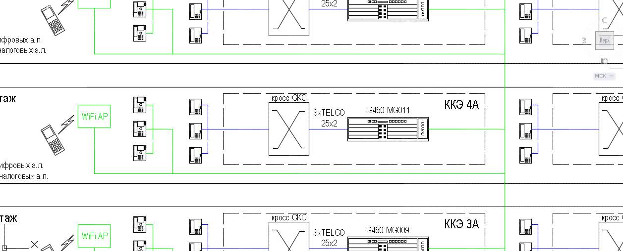
The office of the group companies is located in a building that has 8 above-ground and 1 underground floors. On floors 2 through 8 there are two cross-connected rooms on the floor (KKE), designed to accommodate the administrative system of the SCS, active LAN equipment and telephone facilities.
On the ground floor there is the main cross room (SCC), intended for accommodation, telecommunication equipment, cross fields in telecommunication cabinets, telephone equipment. The GKK also performs the role of the first floor ECC. Cables for external connecting lines were brought into the building into the main cable entry (STB) on the -1 floor. The project was executed in accordance with applicable rules and regulations. The safety of the attendants and the safety of technical means are ensured while observing the measures provided for by the project and the rules for the operation of electrical installations. Technical solutions adopted in the working drawings comply with the requirements of environmental, sanitary, fire and other standards in the territory of the Russian Federation, and ensure safe operation of the facility for the life and health of people, while observing the measures provided for in the working drawings. All equipment and materials used in the design, have the appropriate Russian certificates.
The project was developed on the basis of the following regulatory documents, instructions and standards:
-
GOST R 21.1101-2013 - Basic requirements for design and working documentation;
-
RD 45.120-2000 - Standards of technological design. Urban and rural telephone networks;
-
GOST 21.110 - 95 - Rules for the implementation of specifications of equipment, products and materials;
-
GOST R 21.1703-2000 – Rules for the execution of working documentation wired communication tools;
-
СН 512-78 (amend. 2000g) - Instructions for designing buildings and premises for electronic computers;
-
EIA / TIA-568-B.2-10 - Commercial Building Telecommunications Cabling (technical wiring standard for telecommunication products and services in commercial buildings);
-
PUE - Rules for electrical installations. Edition 7.
1. A brief overview of the technical requirements of the project documentation SKTS
The corporate telephone communication system is a hardware-software complex that provides modern-level telephony of the department and service with telephones, located in the new building of the Customer’s office; The basis of the design decisions is IP telephony technology.
SKTS consists of the following components:
-
Enterprise Automatic Telephone Station (PBX) AVAYA Communication Manager ;
-
Station cross technology and components of SYSTIMAX ;
-
Terminal terminal devices (analog telephone and fax machines, digital (DCP) telephone sets AVAYA , IP / SIPtelephone sets AVAYA );
-
Administrator Workstation with PBX management and monitoring software;
-
AVAYA voice mail subsystem ;
-
Barsum Enterprise telephone call accounting and billing subsystem ;
-
AVAYA conferencing subsystem ;
-
Wireless telephone subsystem WiFi ASCOM ;
The PBX has a total subscriber capacity of 3000 ports, including:
-
Analog subscriber ports - 384.
-
Digital Subscriber Ports (DCP) - 408.
-
IP telephone ports - 2208, of which SIP - 1569
-
The number of wireless subscribers Wi-Fi - 60.
-
You can connect mobile phone applications for smartphones (AVAYA Communicator).
-
The PBX provides connectivity over digital E1 trunks over the ISDN-PRI protocol (EDSS1), IP trunks over the H.323 and SIP protocols.
-
The number of E1 streams is 25 .
-
The number of IP-connecting lines - 120.
Basic technical solutions
The technical solutions used are based on the Avaya Communication Manager CM PBX software 6.3. To improve the reliability of the SKTS, a duplicated processor complex of virtual control servers consisting of two identical servers A and B deployed in the VMware virtualization environment is used .
The virtual environment is organized on a cluster of physical HP DL 360c G9 physical servers with external storage system (DSS) located in the group of computers.
The geographically distributed scheme used implies connecting remote media gateways located in the ECC to the central processing complex A vaya over a corporate data network using VoIP technology .
Session Manager , System Manager , Presence Server , deployed in a VMware virtual environment, are used to connect SIP phone sets .
To organize telephone conferences, a duplicate AVAYA Conference Server deployed in a virtual VMwareenvironment is used .
On a single physical server, the HP the DL 360C the G9 mobile clients deployed server - Client Enablement Server ( CES ), is responsible for the use of SBC phone application the AVAYA CommunicatorMobile.
Description of the equipment
-
Institutional automatic telephone station
The core of SKTS, built on the basis of Avaya equipment , is an automatic telephone exchange. For the implementation of the project's tasks, Avaya Aura Communication Manager version 6.3 (platform S 8800) is used as the PBX . In the Avaya Communication Manager product line , the S 8800 platform is the most high-performance and fault-tolerant.
To ensure the reliability of the processor complex in 99.99%, two servers are used: the main and the backup one. The backup server constantly receives complete information about the current state of the system and changes made to the installations over a high-speed connection (Gigabit Ethernet). Due to this, in case of an accident, the system is switched from the main server to the backup server without interrupting the established connections and without reducing the quality of service. The maximum capacity of the system is 12,000 connecting and 36,000 subscriber lines, and allows you to serve up to 600 thousand calls in the busy hour (CNN).
Starting with version CM 6, Communication Manager server hardware supports VMWare version 4 and higher virtualization environments . As cabinets for connecting subscribers and connecting lines, G450 gateways are used, which are 3U-high constructions mounted in a 19-inch rack. The G450's mainboard contains an internal gateway processor, 160 DSP resources for voice over IP, 64 ports of the tone generator and an embedded “autoinformer” resource, which allows you to organize simple voice menus and play short voice announcements with a total duration of up to 45 minutes. Additionally, you can install one DSP module with a capacity of 160 processors each.
The TDM gateway bus has 412 time slots and allows servicing of 206 simultaneous conversational connections. Media Gateway G 450 has 8 slots for installing Avaya media modules . In order to increase fault tolerance, the media gateway is equipped with the main and backup power supply units connected to the uninterruptible power supply. Telephone sets are connected to the Avaya PBX via an intermediate patch panel on which the TELCO 25 x2 cable is embroidered from analog interface cards (MM716) and digital DCP subscriber lines (MM717).
Each card allows you to connect up to 24 subscriber telephones to the PBX.
-
Telephones
As the terminal subscriber equipment used telephones are listed in Table 1.
Table 1.
|
Telephone model |
Interface protocol PBX |
Nutrition |
|
AVAYA 9608 G |
H.323 |
IEEE 802.3af class2 |
|
AVAYA 9621 G |
H.323 |
IEEE 802.3af class2 |
|
AVAYA 9641 G |
H.323 |
IEEE 802.3af class2 |
|
AVAYA E129 |
Sip |
IEEE 802.3af class1 |
|
AVAYA B179 |
Sip |
IEEE 802.3 af class 3 or stand-alone power supply 220V |
|
AVAYA 1416 |
DCP |
On a subscriber line or a stand-alone power supply unit 220V, using the DBM 32 extension console |
|
AVAYA 9408 |
DCP |
By subscriber line |
|
ASCOM i62 |
Wi-Fi SIP |
Built-in battery |
- model 9608 G
Monochrome display, 8 programmable keys with two-color backlight, 24 function keys. Support H .323 and SIP . Ethernet 10/100/1000 Mbit / s interface , supported G. 711, G 726 codecs (H.323 only), G. 729, G 722. Cyrillic support. Built-in Ethernet switch . Call logging (incoming / outgoing / missed).
- model 9621 G
TouchScreen color display with adjustable angle, 24 function keys. Support H .323 and SIP . Ethernet10/100/1000 Mbit / s interface , supported G. 711, G 726 codecs (H.323 only), G. 729, G 722. Cyrillic support. Built-in Ethernet switch . Call logging (incoming / outgoing / missed).
- model 9641 G
The color Touch Screen display with adjustment of a tilt angle, 24 function keys. Support H .323 and SIP . Ethernet 10/100/1000 Mbit / s interface , supported G. 711, G 726 codecs (H.323 only), G. 729, G 722. Cyrillic support. Built-in Ethernet switch . Support Bluetooth headsets. Call logging (incoming / outgoing / missed).
- model E129
Single-line SIP telephone system. Monochrome display. Support functions Transfer , Forward , Mute , Flash . Support 3-way conferencing. Speakerphone Ethernet interface 10/100 Mbps, supported codecs G. 711, G 723.1, G. 729, G 722. Logging of calls.
- model B179
SIP telephone for conferences. Designed for rooms up to 30 m2. 5-way conference call, the ability to record negotiations on the SD card. Ability to connect remote microphones and wireless headsets. The configuration of the telephone and the setting of the address book is carried out via a Web interface.
- model 1416
This model of the telephone has 16 programmable keys for speed dialing as well as a liquid crystal display that displays information about the opposite subscriber (his telephone number and the name of the subscriber). The telephone is powered by a PBX digital subscriber line.
- model 9408
Monochrome display, 8 programmable keys with two-color backlight, 24 function keys. Speakerphone Supports up to 3 BM 12 extension consoles . DCP interface . Cyrillic support. Call logging (incoming / outgoing / missed).
- WiFi phone Ascom i 62
The protocol used is SIP TLS. Supports 802.11 a / b / g / n, color display, protection class IP44, programmable soft keys. The ability to reprogram using a USB charger. The following AVAYA Communication Manager features are supported: call forward, call waiting, call park, call pickup, EC500, conference, MWI, hold, transfer, call name and caller ID, DND.
-
SIP phone interaction subsystem
Avaya Aura® Session Manager is a software component for routing SIP sessions. It performs bandwidth control, call forwarding, analysis and conversion of dialed numbers, numbering plan management, call billing within the internal network, toll routes bypass, intra-enterprise routing and international routing with the lowest cost of traffic.
Session Manager solves, in particular, the following tasks:
-
Integration:
-
Normalization of network protocols;
-
Integration of third-party solutions and telephone servers;
-
Support for SIP applications, devices and status indication technologies;
-
Scalability
-
From 250 to 250,000 users within a single scalable architecture;
-
Reliability
-
The possibility of expansion in capacity and fault tolerance for building very large and fault-tolerant systems;
-
Simplified Management
-
Centralized network and application administration;
-
Tools for intelligent bandwidth management and network resources.
The structure of SKTS includes Session Manager software in a fault-tolerant configuration, deployed on two virtual servers.
System Manager software is a centralized, secure, WEB-based management console that provides network administrators with an integrated and intuitive solution for managing Session Manager servers . It includes the allocation of resources, user administration, numbering plan management, routing policies, protection and tracking performance ratios and failures, and licensing.
By providing a unified corporate management environment for all users, functions, and applications, Session Manager allows you to achieve better data synchronization, faster deployment, lower cost of ownership, and lower training costs.
Among the main tasks solved by the System Manager software, it is necessary to highlight:
-
Administer up to 250,000 users;
-
Unified management and synchronization with LDAP;
-
Single authorization (Role Based Access Control) to managed subsystems;
-
Monitoring changes made to monitored systems directly;
-
Logging operations performed by the administrator.
The proposed solution includes System Manager software in a fault-tolerant configuration, deployed on two virtual servers.
Virtualization subsystem and computational subsystem (PVVP)
These subsystems provide the computing and storage resources necessary for the operation of the application services of the following SKTS systems:
-
Automatic Telephone Station (PBX);
-
Subsystem interaction with SIP-phones;
-
Teleconferencing system;
-
Voice mail system;
-
Charging system;
-
Mobile client server;
-
Auxiliary systems.
A complete list of SCTS application services hosted on the resources of the virtualization subsystem and the computing subsystem, as well as information on the support of these virtualization services by these services are presented in Table 2.
Table 2. The list of applied services of the SKTS, placed on the resources of the High-Level Conventional Forces.
|
Name |
SKTS system |
Server type |
VMWare support |
|
Communication Manager A |
Automatic Telephone Station (PBX) |
virtual |
Full, but Vmware HA is not supported when both machines are installed in the same VMware HA cluster |
|
Communication Manager B |
virtual |
||
|
System manager A |
Subsystem interaction with SIP-phones |
virtual |
Complete, only based on VMWare |
|
System manager B |
virtual |
Complete, only based on VMWare |
|
|
Manager Session A |
Subsystem interaction with SIP-phones |
virtual |
Complete, only based on VMWare |
|
Session manager b |
virtual |
Complete, only based on VMWare |
|
|
Conference Server A |
Teleconferencing system |
virtual |
Complete, only based on VMWare |
|
Conference Server B |
virtual |
Complete, only based on VMWare |
|
|
Weblm |
Auxiliary system |
virtual |
Complete, only based on VMWare |
|
Utility server |
Auxiliary system |
virtual |
Complete, only based on VMWare |
|
Avaya Messaging |
Voice mail system |
virtual |
Complete, only based on VMWare |
|
Presence server |
Subsystem interaction with SIP-phones |
virtual |
Complete, only based on VMWare |
|
Sal |
Auxiliary system |
virtual |
Complete, only based on VMWare |
|
Barsum Enterprise |
Charging system |
virtual |
Complete, only based on VMWare |
|
Client Enablement Server |
Mobile Client Server |
physical |
Do not support |
In addition to the application services SCTS, the resources of the virtualization subsystem and the computing subsystem also contain service servers, presented in Table 3.
Table 3. The list of service servers PVVP.
|
Name |
SKTS system |
Server type |
VMWare support |
|
vCenter |
Control system of server virtualization complex |
virtual |
Complete, only based on VMWare |
|
vSphere Data Protection |
System backup and recovery of virtual machines |
virtual |
Complete, only based on VMWare |
The virtualization subsystem and the computing subsystem include:
-
server virtualization complex;
-
complex of physical servers.
The block diagram of the virtualization subsystem and the computing subsystem is presented in Figure 1.
5. Server virtualization complex
The server virtualization complex is a hardware-software complex that allows you to ensure reliable operation of the SCTS application services in the virtual infrastructure without changes to the application software using the VMware Essentials Plus Kit software.
The server virtualization complex performs the following functions:
-
ensuring the operation of virtualized hardware compatible with the x86 / x64 architecture;
-
dynamic distribution of computing resources depending on the real needs of each virtual server;
-
ensuring continuity of critical servers, including support for virtual server clusters;
-
automatic restart of virtual servers in case of failure of the physical server;
-
virtual server management (start, stop, reboot) from a single management console;
-
monitoring the use of computing resources of physical servers by virtual servers.
The block diagram of the server virtualization complex is shown in Figure 2.
The server virtualization complex is a group of three HP D L 360c G9 physical servers , with VMware ESXi ™ software installed on each server, and combined in one VMWare HA cluster .
The following software functions on the host servers:
-
VMware ESX i operating system ;
-
VMware vCenter Server Management Server Agent
-
HA High Availability Service Agent.
The list and configuration of virtual servers deployed on the host servers of the server virtualization complex are presented in Table 3.
To ensure high availability of virtual servers, VMware HA (High Availability) technology is used, which allows you to automatically restart virtual machines of a failed physical host server on other host servers. VMWare HA must be disabled for Communication Manager A and Communication Manager B virtual servers . Application virtual machines for which redundancy is provided are hosted on different host servers in a VMWare HA cluster.
-
Control system of server virtualization complex
Virtual infrastructure is managed using the VMware vCenter Server Essentials software included in the VMware Essentials Plus Kit. The VMware vCenter Server Essentials management server is deployed on a virtual server in a VMWare HA cluster in the form of virtual applaince with the built-in DBMS vPostgres . It provides centralized management and monitoring of virtual machines and host servers.
The management system of the server virtualization complex provides:
-
virtual server management :
-
create / delete virtual servers;
-
reconfiguration of virtual servers;
-
create / delete virtual server templates;
-
start, stop, restart the virtual server;
-
configure the VMware HA high availability service .
-
monitoring the use of computing resources of physical servers by virtual servers;
-
redistribution of computing resources of physical servers between virtual servers;
-
delimitation of user access to virtual servers.
-
host server management:
-
monitoring the load of computing resources of host servers;
-
installing and updating the host server OS;
-
OS configuration of host servers;
-
license management virtualization.
-
Rules for calculating physical resources for server virtualization complex
The calculation of the number of required physical servers for server virtualization complex was performed taking into account the requirements listed in Table 5, AVAYA recommendations (2 vCPU = 1 physical processor core with hyperthreding enabled ) and redundantly using the N + 1 scheme. Calculation of disk space for server virtualization complex is made according to the formula: Data volume of virtual servers (see Table 5) + disk space for swap files equal to the size of the virtual memory of virtual servers (see Table 5) + 25% stock for service needs (run backup functions, etc.). The resulting value is rounded up to as many as hundreds of gigabytes.
-
Description of the hardware of the server virtualization complex
HP D L360c G 9 rack servers are selected as the hardware server platform (Figure 3).
Servers are offered in the following configuration:
-
Two Intel Xeon E5-2630v3 processors (8 cores, 2.4GH);
-
Memory DDR4 - 96 GB (6 x 16GB (1x16GB) Dual Rank x4 DDR4-2133);
-
Hard drives 2 x 300GB 6G SAS 10K 2.5in;
-
Controller HP Flexible Smart Array P440ar / 2GB;
-
Four 1GB Ethernet BaseT ports ;
-
One management port 1 GB Ethernet BaseT iLO Management;
-
Five fans;
-
Two 500W power supplies.
The storage system is HP MSA 1040 entry-level storage system (Figure 4).
The storage system is offered in the following configuration:
-
Two controllers;
-
4 ports of 1 Gb Ethernet (2 on each of the controllers), for connecting servers using iSCSI protocol ;
-
11 600 GB 6 G SAS 10 K 2.5 in disks for storing these productive systems. Two RAID5 (4 + 1) groups and one hotspare disk ;
-
7 1.2 TB 6 GB SAS 10 K SFF disks for backing up virtual machines. One RAID6 group (4 + 2) and one hotspare disk ;
-
Two control ports (one on each controller) 1 GB Ethernet ;
-
Two power supply and cooling module.
All equipment is installed in standard 19-inch server cabinets.
The total requirements are given: for power consumption and heat release in Table 6, for network ports in Table 7.
-
Organization of storage of server virtualization complex
To host and load the OS of the host servers, the local hard disks of the DL 360c G 9 servers are used . The configuration of the local disk space of the host servers must comply with the recommendations of VMware (for more information, see “Recommended disk or LUN sizes for VMware ESX / ESXi installations” in Internet: In order to be able to use technology and VMware HA , disk volumes are created on the HP MSA 1040 storage system , each disk volume must be accessible to all host servers of the server virtualization complex. Data disk volumes contain templates and images of virtual servers SKTS.
The possibility of simultaneous sharing of host servers to files located on these disk volumes is provided by means of the VMFS file system, which is used to format the data of disk volumes.
According to the recommendations, AVAYA should use “thick” virtual disks (thick virtual disks).
DESIGN DOCUMENTATION OF TELEPHONY
Table 4 provides information about the disk volumes that should be created on the storage system and allocated to VMware datastore.
Table 4. Parameters of disk volumes created for VMware datastore .
|
Storage system |
Purpose |
Required volume, GB |
RAID type |
Presented to host servers |
|
HP MSA1040 |
Productive |
3000 |
five |
ESXi1-3 |
|
HP MSA1040 |
Backup |
4,000 |
6 |
ESXi1-3 |
-
Network infrastructure of server virtualization complex
The virtual network infrastructure consists of the following components:
-
physical network adapters of host servers;
-
virtual Ethernet switches;
-
virtual network adapters of virtual servers;
-
VMKernel host server interfaces.
Each host server has one HP Embedded 1Gb Ethernet 4-port 331i Adapter four-port physical network adapter. Each server must be connected to two rack-mount network switches, two ports to each. Ports are recommended to be combined into one logical port using VMware ESX i operating system.. Virtual servers of the type standard are created on the host servers. Virtual switches perform the functions of physical Ethernet switches in a virtual environment — the switch determines the source and destination of the packet and uses this information to redirect network packets to the corresponding virtual servers or outside the switch. Each host server has VMKernel interfaces designed to remotely manage a host server by a system administrator using specialized software and the host server interacts with VMware vCenter Server management software, as well as to enable services such as iSCSI, NFS and VMotion to be used. The infrastructure of the server virtualization complex uses vMotion technology, which provides the movement of virtual servers between host servers.
-
The virtual network requirements for the Comminication Manager Communication Manager Duplex link must be separated from the rest of the network traffic. The duplex ports of both Communication Manager servers must be on the same network. To fulfill this requirement should be set up dedicated virtual network to Manager Communication - of VLA of N . For the Duplex link of Communication Manager virtual servers, a separate port group is created.
The following requirements apply to a dedicated Communication Manager network:
-
Total bandwidth should be 1 Gbit / s or more, at least 50 Mbit / s should be reserved for Duplex link;
-
Two-way network latency (round-trip delay) must be no higher than 8 ms;
-
Round-trip packet loss should not exceed 0.1%;
-
The encryption of the channel used for the Duplex link should be disabled during the most busy hours, if it results in a 40% or more load on the Communication Manager server processors;
-
Communication Manager server processors should not exceed 65%.
-
Backup system of server virtualization complex
The backup system is designed to save SKTS data and promptly restore the virtual machines of the complex or its elements in case of emergency situations. Virtual machines are backed up using the VMWare vSphere Data Protection software included in the VMware Essentials Plus Kit. VMWare vSphere Data Protection backup and recovery server is deployed on a virtual server in a VMWare HA cluster as virtual applaince . VMWare vSphere Data Protection provides agentless backup of virtual machine images, as well as backup applications deployed in virtual machines, such as SQL DBMS. Backing up to an HP MSA 1040 storage system using deduplication.
The complex of physical servers is a hardware-software complex that allows to ensure reliable operation of the application services of the SCTS that do not support placement in a virtual environment. The list of such application services is presented in Table 2. The server of the mobile clients Client Enablement Server has the following server configuration requirements: two four = core processors with at least 2.4 GHz memory, 24 GB memory, at least four disks of 146 GB each. It runs under the Redhat Enterprise Linux OS 6.2 and higher. HP DL360c rack server is selected as the hardware platform for hosting the Client Enablement Server .G 9 (Figure 3).
The server is offered in the following configuration:
-
One Intel Xeon E5-2630v3 processor (8 cores, 2.4GH);
-
Memory DDR4 - 32 GB (2 x 16GB (1x16GB) Dual Rank x4 DDR4-2133);
-
Hard drives 4 x 300GB 6G SAS 10K 2.5in;
-
Controller HP Flexible Smart Array P440ar / 2GB;
-
Four 1GB Ethernet BaseT ports ;
-
One management port 1 GB Ethernet BaseT iLO Management;
-
Five fans;
-
Two 500W power supplies.
The server is installed in standard 19-inch server cabinets. Requirements for power consumption, heat dissipation are shown in Table 6, network ports are shown in Table 7.
The server has one HP Embedded 1Gb Ethernet 4-port 331i Adapter, and must be connected to two rack-mounted network switches, two ports each. It is recommended to merge ports into one logical port using OS RHEL (bonding, mode 1 Active / backup).
The PBX equipment is located in the cross-rooms of the floor (ККЭ) and the main cross-room (ГКК).
On floors 2-8 in each CCE, one G 450 is placed in the telecommunications cabinet . Each Media Gateway has one analog subscriber card for 24 ports and one digital DCP subscriber card for 24 ports. Station cross in KKE is made on iPatch patch panels . Each slot of the media gateway, regardless of the installed board, has a TELCO25x2 cable embroidered on the patch panel . The GKK installs 6 G 450 media gateways in which 2 boards of 24 analog subscribers, 3 boards of 24 digital DCP subscribers, and 25 cards of digital E1 connecting lines are placed . Station cross in the GKK is made on iPatch panels. Two slots of each media gateway have TELCO 25x2 cable embroidered on the cross-over panel . The GKK for deploying SKTS applications in a virtual Vmware environment hosts three HP DL 360c G9 servers, an external HP MSA 1040 storage system and one HP DL 360c G9 server for deploying the Client Enablement Server application . The characteristics of the virtual servers are shown in table 5.
Table 5. Characteristics of virtual servers.
|
Virtual server |
purpose |
OS |
HDD, GB |
vCPU |
RAM, GB |
CPU MHzfrequency |
|
Communication Manager A |
PBX server |
Linux (OVA) |
64 |
3 |
five |
2200 |
|
System Manager A |
SIP architecture management |
Linux (OVA) |
120 |
3 |
7 |
2300 |
|
Session manager a |
SIP server |
Linux (OVA) |
90 |
3 |
3 |
1316,667 |
|
Weblm |
License server |
Linux (OVA) |
35 |
one |
one |
2300 |
|
Utility server |
Storage server firmware |
Linux (OVA) |
35 |
one |
one |
2300 |
|
Conference Server A |
Conferencing server |
Linux (OVA) |
150 |
eight |
24 |
2893 |
|
Avaya Messaging |
Voice mail |
Linux (OVA) |
260 |
four |
four |
2000 |
|
Presence server |
Status Server |
Linux (OVA) |
50 |
four |
sixteen |
2400 |
|
Sal |
Remote access |
Linux (OVA) |
220 |
four |
eight |
2000 |
|
Communication Manager B |
PBX server |
Linux (OVA) |
64 |
3 |
five |
2200 |
|
System Manager B |
SIP architecture management |
Linux (OVA) |
120 |
3 |
7 |
2300 |
|
Session Manager B |
SIP server |
Linux (OVA) |
90 |
3 |
3 |
1316,667 |
|
Conference Server B |
Conferencing server |
Linux (OVA) |
150 |
eight |
24 |
2893 |
|
Barsum Enterprise |
Server tarifik and tion |
Win dows Server 2008 St |
500 |
eight |
32 |
3000 |
|
vCenter |
Virtualization Management |
Linux |
150 |
2 |
eight |
2600 |
|
vSphere Data Protection |
VM Backup |
Linux |
150 |
four |
four |
2400 |
The SKTS uses a 6-digit numbering plan. The numbering plan is worked out in detail at the start-up stage.
8. Solutions to improve reliability
The physical equipment of the PBX ( G 450 media gateway , storage system and HP DL 360c G9 server ) has redundant power supplies operating in hot standby mode and connected to independent power feeds. The virtual environment is backed up by VMware mechanisms, using a cluster of HP DL 360c G9 physical servers and external storage. The main components of the PBX , running in a virtual environment - Communication Manager, System Manager, Session Manager, Conference Server - duplicated .
9. Connecting telephone sets and external connecting lines
Analog (fax), digital (DCP) and IP (H.323 and SIP) telephone sets are installed at employees' workplaces. The installation locations of telephone devices of each type are determined at the start-up stage, in accordance with the staffing arrangements. Employee seating schemes are provided by VTB Wireless WiFi phones are intended for employees of operational services and operations of VTB. For connecting to the PSTN, digital trunk lines E1 MM710 are used. Connection to the PSTN is carried out in several independent directions. The number of E1 streams and the signaling protocol, in the direction of each operator, is determined by the specification for connection to the PSTN operator. The minimum number of connecting lines required (at 2% blocking) is 179. A projected PBX is connected to the VTB PBX VTB PBX via IP channels - 30 simultaneous voice sessions (the codec is determined at the stage of preparing the working documentation) and Е1 stream - 30 voice channels. The hardware and licensed capacity allows you to quickly increase the number of voice channels. A PBX being designed by the PBX to other PBXs of corporate telephony VTB can be carried out either via IP channels (SIP or H.323) or E1 channels. The number of connection directions, the number of lines in each direction and the parameters of the channels are determined during the preparation of working documentation. A PBX being designed by the PBX to other PBXs of corporate telephony VTB can be carried out either via IP channels (SIP or H.323) or E1 channels. The number of connection directions, the number of lines in each direction and the parameters of the channels are determined during the preparation of working documentation. A PBX being designed by the PBX to other PBXs of corporate telephony VTB can be carried out either via IP channels (SIP or H.323) or E1 channels. The number of connection directions, the number of lines in each direction and the parameters of the channels are determined during the preparation of working documentation.
10. Ensuring information security TELEPHONIZATION
Information security during the operation of the PBX is ensured by placing the equipment in a room that only authorized Customer’s employees have access to, using dedicated VLAN for the SKTS equipment . The PBX equipment is administered using secure protocols.
11. Interaction with adjacent systems
-
The equipment is installed in a room equipped with a ventilation and air conditioning system that provides an ambient temperature in the range of +18 to +25 ° C with continuous operation. Short-term operation is allowed (no more than 72 hours consecutively or 15 days a year) at ambient temperatures from +4 to +49 ° C. The relative humidity range is from 25 to 80% without moisture condensation. The rate of change of relative humidity of air - no more than 5% per hour.
-
When using an AC source, to ensure the safe operation of the equipment, it is necessary to connect the earthing terminals of the media gateway to the protective earthing bus. The protective grounding bus for connecting the grounding conductor is mounted in a telecommunication cabinet at a height of 0.3 m from the floor. The resistance of the ground loop must not exceed 4 ohms. The power supply system provides the media gateway with uninterrupted single-phase power supply with a voltage of 220V and a frequency of 50 Hz, with maximum allowable voltage fluctuations within ± 10% and frequency deviations of ± 0.4 Hz (according to GOST 13109-87 "Electric energy. Electromagnetic compatibility of technical equipment. power supply systems of general purpose ").Schuko ).
Table 6. Power consumption and heat dissipation.
|
GKK (1st floor) |
|
|
|
|
|
Equipment |
quantity |
Power, W |
total power W |
Heat dissipation btu/ hour |
|
HP DL 360c G9 Server |
four |
50 0 |
2000 |
7644 |
|
MSA1040 Storage System |
one |
337 |
337 |
1174 |
|
Media Gateway G450 |
6 |
530 |
3180 |
10850 |
|
TOTAL |
|
|
5517 |
19668 |
|
|
|
|
|
|
|
Typical KKE (2-8 floors) |
|
|
|
|
|
Equipment |
quantity |
Power, W |
total power W |
Heat dissipation btu / hour |
|
Media Gateway G450 |
one |
530 |
530 |
1808 |
|
TOTAL |
|
|
530 |
1808 |
-
Interaction with a local area network
Media gateways of the PBX are connected via two Ethernet interfaces to the LAN core switches using Bonding technology . Each HP DL 360c G9 physical server connects five Ethernet interfaces to LAN core switches, one of the server interfaces is used only for administration and is in a dedicated VLAN e. The storage system is connected by six Ethernet interfaces to LAN core switches, two interfaces are used for administration in the selected VLANe .
Table 7.
|
Physical equipment |
Management ports number Eth (100/1000) Rj-45 |
Management VLAN |
VoIP ports count eth (100/1000) Rj-45 |
VoIP VLAN |
|
Virtualization Server 1 - HP DL360 G 9 |
one |
SRV-VOIP1 |
four |
IP-PBX |
|
Virtualization Server 2 - HP DL360 G9 |
one |
SRV-VOIP1 |
four |
IP-PBX |
|
Virtualization Server 3 - HP DL360 G 9 |
one |
SRV-VOIP1 |
four |
IP-PBX |
|
CES Server - HP DL360 G9 |
one |
SRV-VOIP1 |
one |
IP-PBX |
|
Storage - HP MSA1040 |
2 |
SRV-VOIP1 |
four |
IP-PBX |
|
G450-1 |
0 |
- |
2 |
IP-PBX |
|
G450-2 |
0 |
- |
2 |
IP-PBX |
|
G450-3 |
0 |
- |
2 |
IP-PBX |
|
G450- 4 |
0 |
- |
2 |
IP-PBX |
|
G450-5 |
0 |
- |
2 |
IP-PBX |
|
G450-6 |
0 |
- |
2 |
IP-PBX |
The assignment of IP addresses to media gateways and PBX application servers is made according to the IP plan.