
The design of heat supply of the laboratory building of the university
We have completed installation, development of the design working documentation and comissioning of the heating system of the laboratory building in Moscow.
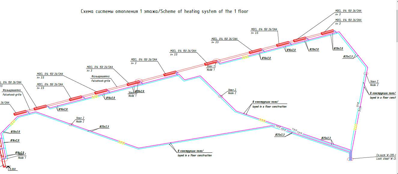
DESIGN OF CENTRAL HEATING SYSTEM
1. Working documentation on the reconstruction and technical re-equipment of production sites for manufacturing and testing.
The working documentation was developed taking into account the following regulatory documents:
- PB 10-573-03 "Rules for construction and safe operation of steam and hot water pipelines;
- SP 41-101-1995 "Design of heat points";
- SP 41-103-2000 "Design of thermal insulation."
2. Working documentation provides for:
- an additional tie-in to the existing thermal comb with the device of the mixing unit.
3. The heat supply of the housing is carried out from the existing central heating point located at elevation. -4,500 in axes 10-11 / AB. The heat carrier is hot water with a temperature of 120-70 ° С. The total contractual load is fj3S kW (4.59 Gcal / h), of which the maximum for heating is 42.90 kW (1.11Gcal / h), for ventilation
3,200 kW (3.25 Gcal / h), the average daily for hot water supply is 268 kW (0.23 Gcal / h).
4. The calculated thermal load on the ventilation system I heating is 720 kW. Since the load has not increased, the projected ventilation system I of the heating is connected to the existing thermal comb.
5. The heat supply of the projected ventilation system II heating in the winter period is carried out from the existing thermal comb with the device mixing unit. The calculated heat load is 110 kW, the parameters of the coolant after the mixing unit are hot water with a temperature of 70-40 ° C.
The mixing unit provides for the installation of two mixing pumps.
TPE 32-250 / 2-S (1-worker, 1-standby) from GRUNDFOS, gate-regulating
fixtures and instrumentation.
PROJECT DOCUMENTATION OF THE HEAT SUPPLY SYSTEM BUILDING
6. In the working documentation accepted pipes:
- steel electrowelded according to GOST 10704-91 for heating and ventilation systems;
- steel water and gas pipes galvanized according to GOST 3262-75 *.
The slopes of pipelines to perform at least 0.002mm. Compensation is decided by the angles of rotation. At the highest points, install air vents, in the lower ones, lower air vents. Pipe joints for welding.
7. Fastening pipelines to perform similarly to the series 5.900-7 c. 4 "Supporting structures and means of fastening pipelines to walls, ceilings and the floor."
8. Production and acceptance of work on the installation of equipment to produce in accordance with the requirements of the technical documentation of manufacturers of equipment and these project drawings.
9. Installation, welding and inspection of welded joints, testing of pipelines should be carried out in accordance with SNiP 3.05.03-85 "Heating networks. Rules for the production and acceptance of work" and SNiP 12-04-2002 "Safety in construction. Part 2. Construction production". After completion of the installation work, the pipelines should be subjected to a hydraulic test for strength and tightness, the pressure of the test, according to SNiP 3.05.03-85, should be 1.25 PP, but not more than 16 kgf / cm2.
10. Upon completion of the installation and test work, isolate the pipelines in coils and tubes of foam rubber of the Armaflex brand. Before applying the insulation pipelines must be cleaned to a shine and painted with oil-bitumen paint for 2 times on the ground GF-021.
11. Installation, welding and inspection of welded joints should be carried out in accordance with SNiP 12-04-2002 "Safety of work in construction. Part 2. Building production".