
Design of the automatic fire alarm system of the training center
Design of automatic fire alarm system implemented by our company in terms of installation and development for the Training Center.
DESIGNING FIRE ALARM
Address-analog fire alarm system is designed for:
· Detecting the occurrence of a fire and (or) smoke site at an early stage of fire development;
· Transfer of the message on the above situations to the fire alarm panel;
· Launch of the fire alarm system;
· Start the smoke removal system in the smoke area;
· Shutdown of general ventilation in case of fire and control of equipment of engineering systems of a building.
2 Main technical solutions of the project
2.1 Applied equipment
The project used equipment manufactured by Schneider Electric.
The system includes:
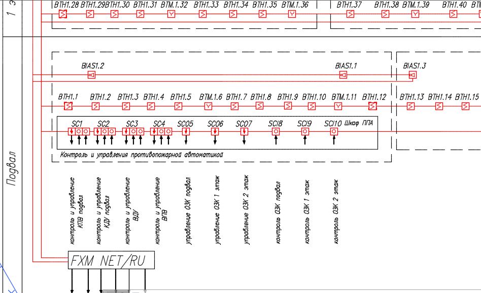
· The address receiving control fire device (ATCM) “FXM NET / RU”;
· Two-channel address control modules with ESMI M221E control channel
· Single-channel address control modules ESMI M210E;
· Addressable control module ESMI M201E-240 DIN; \
· Addressable smoke optoelectronic detectors analog IP 212-131 (ESMI22051E), IP 212-132 (ESMI22051EI)
· Addressable manual detectors - MCP5A-RP02FG-E010-02;
· Fire alarm sounder WMSOU.
The maximum number of addresses in each of the UPKP address lines is 159 addresses for detectors and 159 addresses for modules.
2.2 the Principle of construction
The project provides for the protection of all premises of the complex with an analogue addressable fire alarm system ESMI FX NET (ASPS) regardless of the area, except for the premises:
· With wet processes (showers, bathrooms, sinks, etc.);
· Ventilation chambers (inflow, as well as exhaust, not serving industrial premises of category A or B), pump water supply, boiler rooms, etc. for engineering equipment of the building, in which there are no combustible materials;
· Categories B4 and D on fire danger;
· Stairwells.
In accordance with paragraph 13.2.2 of the joint venture 5.13130.2009 rev. 1 The maximum number and area of premises protected by a single ring or radial loop with address fire detectors is determined by the technical capabilities of the control equipment, the technical characteristics of the detectors included in the loop and does not depend on the location of the rooms in the building.
In accordance with paragraph 14.2 SP 5.13130.2009 rev. 1 the formation of the management team of 14.1 (launch of the 4th type warning system, the start of smoke removal) is carried out from one fire detector, the placement of the detectors in the room is carried out at a distance not more than the normative, determined according to tables 13.3 and 13.5 of the joint venture 5.13130.2009. one.
In accordance with paragraph 14.3 of the joint venture 5.13130.2009 rev. 1 generation of control signals in the automatic mode of the fire extinguishing installation in the protected room is established by at least two fire detectors when they are turned on in the loops of addressable devices and subject to the timely replacement of the faulty detector. At the same time, the placement of the detectors should be carried out at a distance of no more than half of the normative, determined according to table 13.3 of the joint venture 5.13130.2009 rev. one.
As a means of detecting a fire in protected premises, an analogue optoelectronic smoke detector IP 212-131 (ESMI22051E), which reacts to particles of solid or liquid products of combustion and pyrolysis in the atmosphere, installed on a suspended ceiling, has been adopted.
The project provides for installation of targeted manual fire detectors MCP5A-RP01FG-E010-02 in the corridors and building exits on the walls, at a height of 1.5 m from the floor level. Manual fire detectors are installed at a distance of no more than 50 m from each other.
In order to reduce the effects of short circuits, smoke detectors with a short-circuit localizer IP V2 212-132 (ESMI22051EI) are installed in the address loops of the FPGA via 25..30 addresses.
The interconnection of AUPS with other systems, technological and electrical equipment of the building is provided by the formation of the following commands:
· To start smoke removal in case of smoke in the smoke removal area;
· To launch a warning system and evacuation management in case of fire;
· To disable general ventilation;
· To lower elevators to the main landing floor;
· To unlock the doors to the access control system;
· To unlock the main entrance doors;
· The signal "fire" in the unit responsible for the fire protection of the object.
The use of these commands in the management of engineering systems of the building is performed on the instructions for the management of engineering systems of the building.
2.3 Equipment placement
On the ground floor, in the reception area, an ARPA “FXM NET / RU” is installed. The ASPS equipment is mounted on the walls, the height from the floor level to the operational controls is 0.8–1.5 m, the clear distance between adjacent devices is at least 50mm.
The control and monitoring modules for the smoke-free and fire-retardant protection ESMI M221E, ESMI M210E, ESMI M201E-240 DIN are installed on DIN rails in a wall-mounted cabinet in the server room.
3 Power supply
In terms of power supply reliability, consumers of an automatic fire alarm system fall into category I.
The projected building is an object of III category of reliability. To ensure the operation of the ASPS system, installation of two batteries with a total capacity of 12 Ah is provided in the ATCCF case. Selected batteries allow the system to operate 61h. in standby mode.
The building provides power supply ~ 220 V, 50 Hz of the ASPS equipment from the power board projected in section 12Р-01-1-ЭОМ according to the instructions for power supply and grounding (page 7 of this section).
4 Activities for the safe operation and maintenance
The installation, installation, testing, maintenance of electrical equipment of the ASPS installation should be allowed to persons having an electrical safety group not lower than III for voltages up to 1000 V. All installation work and work related to troubleshooting should be carried out only after the equipment is de-energized. During operation, it should be borne in mind that the “220V” terminals are under life-threatening voltage and require special attention. Electricians serving the electrical installation must be provided with protective equipment that has passed the appropriate laboratory tests. Protective grounding is carried out according to the task for power supply and grounding (sheet 7 of this section).
5 General requirements for the installation
Electrical installation work should be performed in accordance with the requirements of SP 5.13130.2009 Amendment 1, RD 78.145-93, SNiP 3.05.06-85 * and ПУЭ.
The choice of wires and cables, methods of their laying for the organization of loops and connecting lines of the fire alarm system was made in accordance with the requirements of ПУЭ, section 13 СП 5.13130.2009 amendment 1 and technical documentation for the instruments and equipment of the system. Fire alarm loops are made by independent cables with copper conductors.
The project provides for the implementation of:
· Address loop of ASPS - cable KPSEng (A) -FRLS 1x2x0.75;
· Lines of automation - cable KPSEng (A) -FRLS 1x2x0.75;
· Valve control lines and power supply network ~ 220V - cable VVGng-FRLS 3x1.5.
The project provides the following methods of cable laying:
· Behind a suspended ceiling in a horizontal direction in PVC corrugated pipe;
· Descents to the instruments and manual detectors in the wall with the protection of the corrugated tube;
· In the vertical direction between the floors in a steel pipe with a diameter of 50mm;
· Passages through the main walls in a horizontal direction in a steel pipe.
When the cable passes through the walls, the cable must be laid in embedded tubes made of steel pipes. The gaps in the sleeves after laying the cables should be sealed with sealing paste for cable passes of the MGKP. The ends of cable penetrations and the surface of cables protruding from the penetration should be treated with a flame retardant MPO for a length of at least 200 mm.
6 Environmental protection activities