
Design electrical system for administrative building
Completed installation and design of the power supply system, diesel power plant in the administrative center.
Details below ..
DESIGNING ELECTRICAL
1. Switchboard equipment.
1.1. Guided by the agreed project Cipher P1-1408-12-IOS 1.1; P1-1408-12-IOS 1.3; P1-1408-12-IOS 1.4, by the layout decision and the present to carry out the manufacture and supply, installation supervision and commissioning of the ATS and switchboard equipment to the object.
1.2. Develop the layout of ASU and switchboard equipment, taking into account the placement of equipment in the premises indicated on the layout. All decisions agreed with the customer.
1.3. Layout solutions for all switchboard equipment should take into account the ability to connect the required number and cross-section of cable lines in accordance with the project.
1.4. All solutions must meet the requirements of both the possibility of free installation and further safe operation of the equipment.
1.5. Input and output of distribution cable lines of equipment ASU - top.
1.6. In the manufacture of HS) take into account that the distribution cabinet is located on the street.
1.7. To organize the operation of the ATS circuit, use a controller with the ability to monitor the status of the contact group via the Ethernet network. Provide its own power source for the controller to ensure galvanic isolation from the network. Additionally, provide the ability to connect the controller from the power system inverter installed in the room (UPS). Mark the terminal box for connecting uninterrupted power supply from an external UPS in the appropriate way, reflect it in the passport.
1.8. When picking a VRU-0.4 kV with automatic transfer switch, provide electronic and mechanical interlocks between the switching on of inputs.
1.9. Time delays and the algorithm of ABP work, coordinate with the Customer.
1.10. The ATS should also include alarm lamps, control buttons, mode switches (A-0-P), ATS should provide the ability to set the input priority.
1.11. Develop and provide the Customer with the user manual of the ATS (on paper and electronic media).
1.12. The structure of the algorithm ABP is specified in the project.
1.13. For all equipment to provide passports and relevant certificates.
1.14. All boards, panels, cabinets, switching devices, etc. must be labeled accordingly. Shield equipment must be equipped with diagrams.
3. ELECTRICAL REQUIREMENTS
3.1. Prior to the commencement of work, all changes to design decisions, including the materials used, products and equipment, should be coordinated with the Customer and the developer of the project documentation.
3.2. Deliver equipment to the site.
3.3. Perform installation supervision of equipment.
3.4. Perform commissioning of automation ASU-0.4 kV.
3.5. In the process of production of works to maintain the production and executive documentation, which to transfer to the Customer when transferring equipment in the following form and quantity:
- on paper in 2 copies;
- on electronic media in 1 copy.
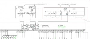
Work scheme: In the operating mode, the transformer points are powered by the existing lines from the MSB. With the disappearance (absence) of voltage on any of the supply lines (1.2 or 3, 4, 5) for more than 150 seconds, the ATS should give a signal to turn on the diesel generator set and power the “problem” line. If another line is de-energized, then the ATS should also power it from the diesel generator set, etc. up to complete shutdown.
When eliminating the causes of failure in the reserved DGU line and the resumption of power supply from urban networks, the ATS should continue to supply the previously de-energized line from the DGU for 600 seconds and only after that it will switch to power from the city networks.
In addition, it is necessary to protect against overloading each line connected to the DGU with a circuit breaker of the appropriate rating.
The mains parameters are shown in the diagram: peak power Pn = 254 kVA
DGU power: Rdgu = 275 kVA