
Design of electrical power supply for a checkpoint
The design of the electrical power supply system EOM, which we designed and installed at the checkpoint.
DESIGNING EOM CAT
The list of regulatory documents in force in the territory of the Russian Federation containing requirements for this object:
PUE "Broke the device electrical installations (7th edition)";
SP31-110-2003 "Design and installation of electrical installations of residential and public buildings"
SNiP 3.05.06-85 "Electrotechnical devices";
"Intersectoral rules on labor protection (Safety Rules) for the operation of electrical installations" POT RM-016-201,
RD-153.34.0-03.150-00;
SNiP-3.05.06-85 "Electrotechnical devices"
SNiP 12-04-2002 "Labor Safety In Construction";
GOST R 21.1101-2013 "Basic requirements for design and working documentation."
The list of types of work that have an impact on the safety of structures, for which it is necessary to draw up certificates of examination of hidden works, responsible structures:
- Laying of group lines in the preparation of the floor.
- Laying group lines for suspended ceiling.
- Installation of cable structures behind the suspended ceiling
PROJECT DOCUMENTATION EM
Laying the outer ground loop
Works on corrosion protection of welded joints (if necessary)
All materials, products, equipment must be appropriate passports and certificates.
Power supply
The design of the checkpoint by the degree of reliability of power supply refers to consumers of the 1st category. For individual consumers of STN, ASDU, SPD systems, according to the TOR, the UPS is provided with the Operating Time of 3 min.
Technical and economic indicators of the project:
- useful area of the building
- installed power
- rated power
- installed lighting power
- voltage class
- reliability category
1563kW
947kW / 1007.5kVA
30.6kW
220 / 380V
- type of grounding system
TN-C-S
Internal power supply
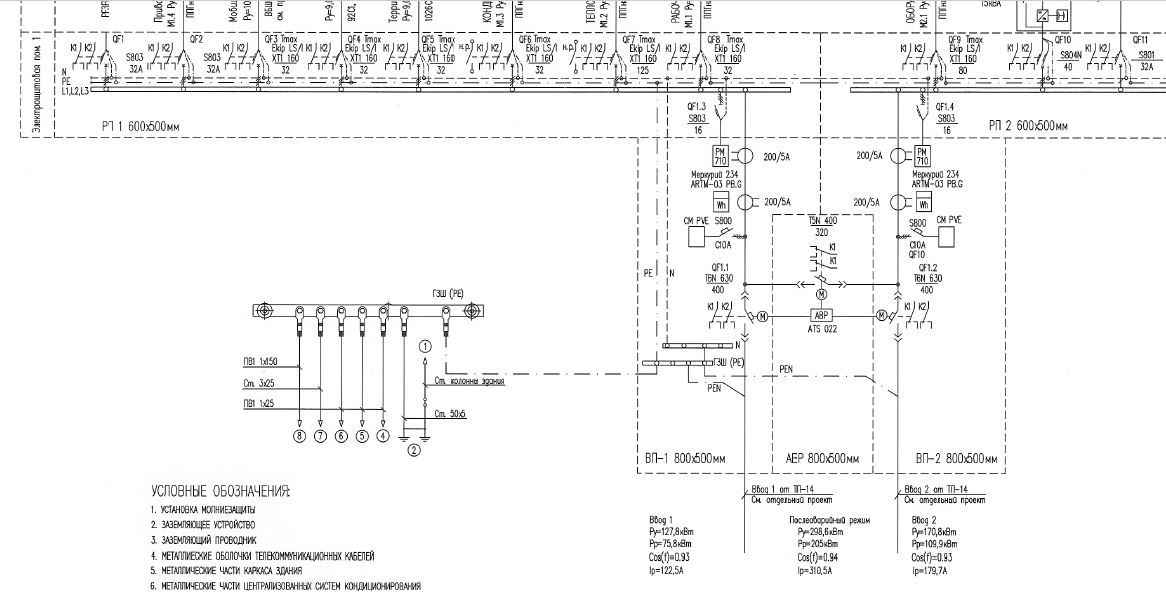
In the design of the CAT provides for the installation of 6 input distributing devices VRU:
VRU1.1 and 2VRU1.1 6 G1.1; VRU1.3 in G1.3, VRU1.4 8 G1.4; VRU1.5 in G1.5. All ASUs are located in a separate
electrical room, each of which has a separate entrance from the screening room. Horizontal
distribution wiring is provided openly in trays indoors
switchboard. Lighting networks in the inspection area are hidden behind a false ceiling in PVC
pipe and tray, in pom-and SS, electrical - open in the cable channel. Group power networks
performed from group shields in a metal tray behind a false ceiling; to hatches in
mortgage boxes in the preparation of the floor, to the radiators are hidden in the tray, downs - openly
cable channel. Embedded boxes, trays, cable channels, recessed sockets and hatches included
section CCM.
Supply lines and group networks of SDR systems and emergency lighting are made with cables.
PPGNG (A) -FRHF, the power supply network and distribution lines of the remaining power consumers are made
cable PPGHG (A) -HF.
Equipment installation height (from the level of the clean floor to the center), except those indicated on the plan:
• plug sockets for heating radiators - 200mm;
• other receptacles - 900mm, unless otherwise indicated on the plan;
• group shield - 1600mm;
The project provides for the shutdown of air conditioning systems and heat curtains in case of fire.
For what on outgoing lines in the VRU installation of independent release 220V is provided.
Disconnection occurs on the signal "Fire", the inclusion is made by the operational staff, after
cancel signal fire alarm.
Electricity metering
Commercial accounting of electricity is provided for a separate project in accordance with the specifications for accounting.
Installation instructions for protecting people from electric shock include the following means and measures:
The main insulation of current-carrying parts; Guards and enclosures;
Warning signs, signs and labels;
Restricting the access of unauthorized persons to electric rooms;
Zanulenie conductive electrical enclosures, switchboards;
The system of basic and additional equalization potentials;
Application of a residual-current device controlled by a differential current, with a set of DIRECTIONS on power lines of sockets, portable electrical receivers and electrical equipment in rooms with increased danger;
- Application of extra-low voltage (36V) for portable repair devices
lighting;
Grounding and lightning protection
Lightning protection category of the building - III. As lightning receiver use
lightning-resistant mesh (round galvanized conductor 08mm), with a pitch of cells no more than 10x10m,
fixed by the holders of the conductor on the surface of the roof.
As the current leads - metal columns of the building with the release from them at mark. 0.000
metal strip 25x3 mm in increments of not more than 20 m on the external ground loop. On the roof
The columns are connected to a lightning receiving grid.
2. All connections should be made by welding in accordance with GOST 5264-80; all weld joints in the ground cover
bitumen mastic
3. All towering metal elements of the building should be connected with roof meta-structures;
4. Welding produced by electrodes