
Project of ventilation and smoke exhaust in a business center
Our design organization has developed documentation of ventilation and smoke exhaust in a business center.
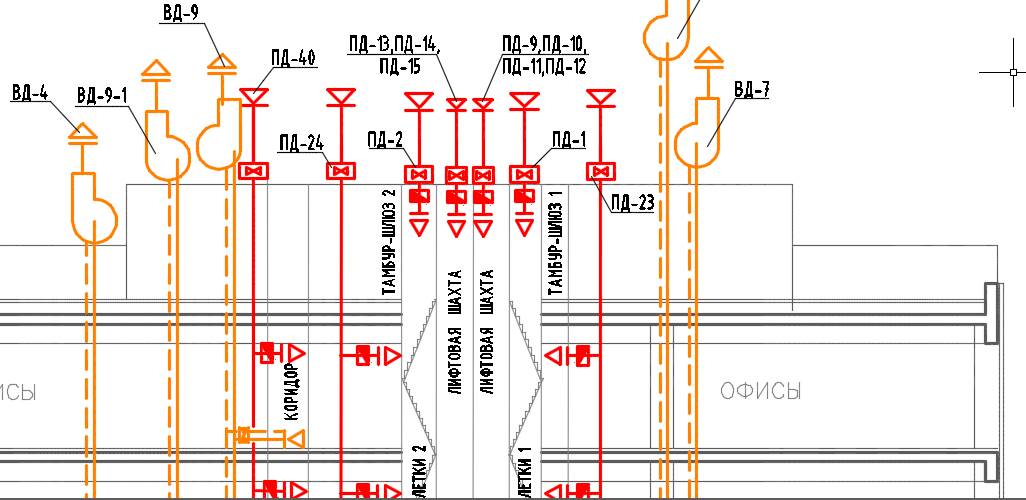
DESIGN OF SMOKE EXHAUST AND OVERHEAD
Functional purpose of the smoke ventilation of the building
According to the space-planning design and the fire safety regulations in force, the following main functions must be provided by means of the smoke-extraction ventilation of the object in question:
- Removal of combustion products from the vehicle storage rooms of the underground parking lot;
- Removal of combustion products from isolated parking underground ramps;
- flue gas removal from the common technical and service corridors in the underground car park; flue gas removal from the isolated parking lofts; flue gas removal from the isolated
of the common corridors of technical and service rooms located on the underground and lower aboveground floors;
- Removal of combustion products from the common corridor of service facilities (security, control room), located on the lower aboveground floor;
- removal of combustion products from the common corridors of the offices of the above-ground part;
- De-extraction of combustion products from the common corridors of the above-ground part of the aparthotel;
- supply of outside air to the lower part of the car storage rooms of the underground parking lot to compensate for the volumes of combustion products removed from them;
- supply of outside air from the isolated ramps on the side of the underground parking car storage rooms, as well as in the lower part of these ramps to compensate for the volumes of combustion products removed from them;
- supply of outside air to the lower part of the common corridors of technical, service and technological premises of the "public catering area", to compensate for the combustion products removed from them;
- the supply of outdoor air to the lower part of the vestibule, a two-level lobby of the above-ground part to compensate for the volume of combustion products removed from them;
- supply of outside air to create excess pressure in the vestibule airlocks at the exits to the stairwells from the car storage rooms of the underground parking lot;
- supply of outside air to create excess pressure in the vestibule airlocks separating the car storage rooms of the underground parking from the rooms of other purposes (including staff rooms and pump rooms);
- supply of outside air to create excess pressure in the elevator lobbies communicating with the car storage rooms of the underground parking lot;
- supply of outside air to create excess pressure in the elevator shafts which have stops on the underground parking floors (with exits through the elevator halls to the car storage rooms) and the lower above-ground floor;
- supply of outside air to create excess pressure in the elevator shafts that have stops in the above-ground part;
- supply of outside air to create overpressure in elevator shafts that have stops in the above-ground part;
- supply of outside air to create overpressure in the common corridors of the offices of the above-ground part;
- supply of outside air to create overpressure in the stairwells communicating with the common corridors of the offices of the above-ground part.
In order to eliminate the dependence on the seasonally changing parameters of the outdoor air environment and, consequently, to increase the efficiency of the smoke ventilation of this object, systems, mainly with mechanical draft inducement, should be provided.
The use of double-deck car parking with lifting and rotating mechanisms envisaged by the project predetermines the need to intensify the calculated modes of action of both exhaust and supply smoke ventilation designed to protect the car storage premises of the underground parking lot.
At the same time the parameters of corresponding systems should be linked with the predicted heat release power of fire focuses ("doubled" up to 10 MW heat release power for two-tier parking under the condition of combustion of both vehicles stored above each other), and elements of these systems should be aligned with a number of essential features, including: an increased number of smoke-extraction devices, placing the latter in a limited under-ceiling space (within the formed relatively thin space).
The compensation of volumes of exhausted combustion products from vehicle storage rooms and isolated parking garage ramps, general corridors of technical, service and technological facilities on the underground floors and general office halls on the above-ground floors within the framework of this development is achieved by applying separate systems of forced-air smoke ventilation with mechanical draft control providing fresh air supply to the bottom part of each room protected in this way. The required flow rate of the supplied air should be at least 70% of the design values of the total mass consumption of combustion products removed from the premises.
Common corridors of service and technological rooms of the lower above-ground floor and common corridors of offices on the upper floors may not be equipped with independent systems of supply smoke ventilation, taking into account the calculated sufficiency of the compensating air flow through the doorways of the evacuation exits;
The established basic functions of smoke ventilation of the facility in question correspond to the design space-planning solutions with the following objectively necessary partial changes:
- additional allocation of ventilation chambers on the underground floors;
- additional partitioning with doors to separate the common corridors of the offices.
The other design volumetric-planning elements are accepted within the framework of this development initially unchanged. Any change in the latter requires an additional analysis of the totality of the input data to determine the required scope of the content and results of this design. Without such an analysis, the design implementation of the developed technical solutions and established parameters of smoke ventilation for this object is not allowed.
Smoke ventilation
The design includes fire protection measures in accordance with the Special Technical Conditions (STC) for design and reconstruction, as well as the Smoke Control ventilation concept and regulatory requirements.
The smoke protection solutions for the complex stipulate the installation of mechanical smoke removal and air overpressure systems, which enable the safe evacuation of people at the initial stages of a fire.
The complex building is divided into 4 fire compartments (see Section 1, "General Part" of this Explanatory Note). There are separate smoke and air-supply systems for each fire compartment.
The mechanical smoke evacuation systems are provided from the following areas and rooms:
- from the two floors of the two-level parking lot ( 2 compartments);
- from the upper part of the ramp;
- from the evacuation corridors of the underground and above-ground parts;
- from the office part of the building;
- from a part of the aparthotel;
- from the dining room and restaurant.
To compensate for the volume of exhausted combustion products for these areas is achieved by using separate systems of supply smoke ventilation with mechanical draft control, providing the supply of outside air in the lower part of each of the protected rooms, as well as provides for air in case of fire:
- in all elevator shafts regardless of elevator lobbies (at least 20 Pa);
- in evacuation corridors;
- elevator halls and in the safety zones for disabled people;
- to stairwells;
- to the vestibule airlocks of the parking lot;
Smoke exhaust systems are equipped with special fans ensuring operability within 2 hours at gas temperature of 600°C. The installation includes equipment by "VEZA" (Russia).
Smoke exhaust fans shall be installed on the roof of the building. The smoke is discharged at the height of more than 2 m from the combustible roof and at a distance of at least 5 m from the air intakes of smoke removal ventilation systems.
The installation of non-return valves at the fans of smoke removal and air overpressure to prevent the entry of cold air into the premises is provided.
One shaft of the smoke exhaust system serves the smoke zone of not more than 3,000 m² on each floor within the fire compartment.
Smoke exhaust dampers are accepted with automatic and remotely controlled actuators without thermocouples. Electrically operated reversible dampers are used as normally-closed dampers.
Smoke exhaust and supply smoke ventilation systems use smoke (normally closed) valves with electromechanical actuator Velimo CJSC (Russia), which can be operated automatically, remotely and manually.
All fire protection systems, including also fire dampers and smoke-removal dampers, are controlled from a single central control station.
Ducts of high pressure systems are made of thin sheet steel 1.5 mm thick, welded, of class "P", and covered with fire retardant composition within served fire compartment up to fire resistance EI 60, outside served fire compartment up to fire resistance EI 150 (in accordance with SP 7.13130.2009).
Ducts of AP systems are made of thin sheet steel of thickness by SP 60.13330.2012, but not less than 0.8 mm, class "P". They are coated with fire protection composition within the serviced fire compartment to fire resistance EI 30, outside the serviced fire compartment to fire resistance EI 150 (in accordance with SP 7.13130.2009). and fire resistance limit of the valve: in the Fire retardant (smoke) damper - EI 90 / E 90; in fire normal closed damper - EI 30.
The smoke ventilation systems of the building use equipment produced in the Russian Federation, which has certificates of compliance and fire safety.
Sound and heat insulation materials of the smoke ventilation equipment are made of non-combustible materials.
Supply and exhaust ventilation, air conditioning and air heating systems are automatically turned off in case of fire in the building and smoke removal and air overpressure systems are automatically turned on. In addition, manual actuation of systems in case of fire is provided.
The main parameters of the purpose of smoke ventilation and the corresponding required values of these parameters are described in the calculations below. The required values of the supply and exhaust smoke ventilation are in accordance with the table calculations given directly for the volumes (rooms) to be protected.
These values must be taken into account as input data for the final determination of the main parameters of the fans, depending on the selected technical characteristics and design elements of the ventilation network of the smoke ventilation systems in the subsequent stages of design.
Smoke extraction ventilation
This annex contains basic and intermediate results for estimating the required parameters of smoke ventilation for the "Hotel and Office Complex with underground Car Park" to be built. The content of this appendix is of illustrative and applied nature and can not be reproduced in the calculations of the required parameters of smoke ventilation systems of other similar facilities.
Performed calculations are given in two main parts: for the systems of exhaust and supply smoke ventilation - separately and in the lists of free sampling for each type of system. During the calculations, the aerodynamic resistance of the network of each system was determined in strict accordance with the geometric characteristics established by this development and the routing of ventilation ducts, according to the recommended
Smoke extraction from the underground parking lot.
Let us consider an example of calculation of smoke removal systems from the underground parking of fire bays 3 and 4 (PO3 and PO4). Calculation of the smoke exhaust and supply ventilation systems in case of fire of the underground parking lot for 100 cars under the building.
Here is presented a calculation of the smoke ventilation systems in case of fire (hereinafter referred to as Smoke Removal Systems) VD3, VD4, VD6 and VD7 of the underground 2-level parking lot and the supply smoke removal systems of ramp PD20 for CP3, PD21 for CP4 and tambour sluices of all exits PD30-PD34, PD36-PD38 for CP3 and PD25-PD29 for CP4 from the parking lot with non-asbreathing stairwells of H3 type. In the calculation, the ground floor was taken as the floor where the fire occurred. When calculating the smoke coming from the seat of fire, it was assumed that the perimeter of the seat of fire is 12 m (the maximum recommended in Appendix [11]). The amount of smoke is calculated according to [5], item 1.3.
Smoke removal from parking premises. In accordance with paragraph 6.15 of SNiP 21-02-99 it is necessary to provide anti-smoke ventilation systems for removal of combustion products from the car park premises and isolated ramps. To remove smoke from the parking lot premises (car storage rooms) there shall be provided 1 smoke evacuation shaft (FOBSL = 900 m2). The fire resistance of the smoke exhaust shaft shall be not less than 0.754, and the damper not less than 0.54.
Under the building there is a two-level parking lot for 299 cars. Levels of -8.700 and -4.550. The exit ramp has two lanes, forward and reverse, and has two exterior exit gates at ground level (one exterior gate per lane). There is no airlock in front of the exterior exit gates.
Exit gates from each floor to the ramp are single, and have a breech system to protect the opening. The total area of the parking lot 8291.2 m², height: lower 3.65 m, upper 3.85 m. The underground parking lot has six exits to the outside with 2 storey stairwells type H3 (with floor exits from the floors through vestibules-gateways). At ground level, stairwell exits end with a door to the street. There are passenger elevators in the underground parking lot.
When calculating the ventilation of smoke protection, outdoor air temperature and wind speed for cold and warm periods of the year was taken according to parameters B for Moscow; wind speed is taken equal to 4.9 m/s in the cold period of the year. For smoke evacuation systems, when determining the gravity pressure, the outdoor air temperature was taken as the design temperature for the warm period of the year. In accordance with the requirements of para. 8.15 (a), [1] the calculation of the supply smoke ventilation was carried out for the outside temperature and wind speed in the cold period of the year (parameters B).
Fire hazard of the parking lot premises is attributed to the category of premises B, so in the calculation was taken the temperature of smoke exhausted in a fire equal to T = 450 0C according to the recommendations [5], and the average specific weight of smoke is taken = 5 N/m3, density of 0.51 kg/m3.
Smoke exhaust fans BD3, BD4, BD6 and BD7 are placed on the roof of the building. Smoke exhaust system supply ducts in front of the fans for interchangeability are connected by a manifold. The connecting collector is separated by smoke dampers for automatic activation of the connected fan of the adjacent system during an emergency stop of the main one (redundancy in accordance with clause 1.10 [5]). Check valves are provided in the ducts in front of the fans.
As required by p. *3.20 [3], adopted in the project exhaust fans of smoke removal systems retain their performance at a temperature of 600 0C for at least 1 hour.
In accordance with para. *3.20 [3] and item 6.20 [4] each branch of smoke exhaust systems VD3, VD4, VD6 and VD7, going to the smoke tank is equipped with normally closed automatic smoke damper type KDM-2-1000x500-MB-VN-V-K-R (A) VINGS-M with through passage section of 0.44 m2 with a servo drive Belimo and a fire resistance limit EFI 60. The number of smoke exhaust valves below is determined by calculation. The fire-resistance limit of smoke exhaust shafts shall not be less than the required fire-resistance limits of intersected ceilings, and floor branches of ducts from shafts shall not be less than EI 60.
Smoke protection systems shall be put into operation in accordance with clause *3.19 [3]. *3.19 [3] is performed automatically (from an automatic fire alarm or automatic fire extinguishing system) and remotely (from a dispatcher's desk and from buttons installed in cabinets of fire hydrants or at the evacuation exits from the floors).
In the vestibule-entrances in front of the stairwells of type 3 exits from the underground parking lot during a fire (p. 2.7.4, [7] and p. 3. 17, [5]) the inflow of external air for each ventilation system from AP20, AP21, AP25, AP26, AP30-PD34, AP36-PD38, AP27-PD29 is carried out through a vertical shaft collector with automatic valves installed on each floor and opened at the signal of a fire alarm system on this floor. Smoke dampers are used as supply dampers.
We suggest using smoke dampers with vertical orientation of the largest side, "wall" type KDM-2-900x500-MB-VN-V-K-R (B), (or in cramped places 1150x400) with a grid and a through passage section S k = 0.39 m2. The valve is installed directly on the vertical 1500x550 sheet steel channel (dEKB = 805 mm; SQ = 0,509 m2). The valve is supplied with Belimo (or Polar Bear) actuator. In the duct before the axial flow fan a smoke valve with electromechanical servo drive of 1100 x 1100 mm cross section is used as an inlet valve as well.
According to para. *3.18 [3] in underground multi-storey parking lots in order to ensure efficient operation of smoke removal systems, shafts should be designed for the natural entry of outside air to the fire floor.
To protect evacuation routes from smoke penetration in case of fire in the underground parking lot there shall be forced ventilation of smoke removal separately for the ramp (ramp) PD20 and
All doors of stairwell airlocks of H3-type stairwells of parking lot exits shall be equipped with automatic closing devices as required by paragraph 6.18 [2] (see further in (l)). Door closers (any of DORMA, USAF, ABLOY, ASSA, GEZE, etc.) can be accepted as such devices. For doors with the width up to 1100 mm and the weight up to 85 kg according to the European standards the door closer is equipped with EN4 spring with which it develops the closing force moment not less than 25 Nm, i.e. the force of about 2.5-3 kg is required to open the door when pressing it near the handle.
In accordance with paragraph 6.18 [2]: "Doors of evacuation exits from floor corridors, halls, foyers, lobbies and stairwells shall not have locks preventing them from being freely opened from inside without a key.
Doors of stairwells to common corridors, doors of elevator halls, and doors of air locks with permanent air supply shall have devices for self-closing and sealing at the gates, and doors of air locks with fire air supply and doors of rooms with forced smoke protection shall have automatic devices for closing them in case of fire.
According to the requirements of clause. 8.14 (c) of [1], given paragraph 6.18 of [2] and in accordance with the recommendations of paragraphs 1.11 (c), (d), (e) of [5] the following condition of the doors and gates of an underground parking lot in case of fire has been taken for the calculation of the supply ventilation system of smoke protection:
- On the fire floor (lower), the door leading to the parking lot is open in the vestibule-gateways of the stairwell type H3, and the door leading outward is closed;
- In the vestibule air locks of the upper floor of the parking area, both doors are closed;
- The air flow rate to airlocks with one open door shall be calculated according to the condition of ensuring the average velocity (but not less than 1.3 m/s) of the air flow through the open doorway and taking into account the combined action of the smoke exhaust ventilation (p. 8.14(c) of [1]).
When the doors are closed, the airflow to the air locks shall be calculated for the air leakage through the door leaf leaks. The overpressure value should be determined relative to adjacent rooms with the protected room (p. 8.14 (c) [1]).
- The vehicle exit gate to the ramp on the fire floor is fully open. The sprinkler system for protecting the gate opening is on.
- Exterior vehicle exit gates outside the parking area are fully open.
- The gate for exiting cars to the ramp on the other floor of the parking lot is closed.
According to the requirements of par. 8.14 (c) of [1] (see previous paragraph (l)), the rate of outside supply air of smoke control systems for vestibule-gateways of stairwells on the fire floor (with one open door per floor in each) is determined from the condition of maintaining a flow rate in the doorway not less than the minimum allowed 1.3 m/s and taking into account the combined action of exhaust smoke ventilation.
The overpressure on the closed doors on the escape routes (for the doors of tambour airlocks, the opening of which is prevented by a back pressure) shall not exceed 50 Pa (according to p. 1.13 [5]), but shall not be less than 20 Pa (see p. 8.15 (b), [1]); the pressure is controlled by an overpressure valve (door with door closer, M~25 Nm, with EN4 spring).
According to p. 1.11-1.14 [5] and p. 2.5.1 [7], and according to the state of the doors and gates in a fire (see p. (l) above), the pressure and flow rate of the supply air from the smoke control system of the ramp PD20, PD21 is calculated for counterpressure to the outside air and with consideration of the combined action of the smoke removal ventilation and the smoke control air supply systems of the vestibule-entry stairwells on the fire floor.
The entire calculation of the capacity of the working smoke protection systems (exhaust and supply) is controlled by the balance of air exchange on the fire floor.
This takes into account, and in full compliance with Section 6.18, [4]: "In case of fire there shall be provided for disconnection of the general exchange ventilation of the underground parking.
The order (sequence) of activation of smoke protection systems shall provide for preemptive start of exhaust ventilation (before supply ventilation).
When determining the capacity of smoke protection ventilation systems, air leakage through leaks in the air ducts shall also be taken into account.
Input data:
The number of floors of the building of the hotel and business complex.
(H = 51,2 m). Under this building is placed 2-level two-story parking for 100 cars.
The height: the lower 3,65 m, the upper - 3,85 m. There are passenger elevators in the underground parking.
Exit ramp has two lanes, in forward and reverse directions. There is no ramp gate in front of the exterior exit gates.
Exits from each floor to the ramp have a deluge system to protect the opening.
The underground parking lot has six exits to the outside with non-smoke 2 storey stairwells type H3 (with floor-level exits from the floors through vestibule-gateways). At ground level, the stairwell exits end with a door to the street. The dimensions of the entrance doors are B = 1.2 m; H = 2.2 m.
Calculated temperature of external air in the cold season of -25 º C, wind V = 4.9 m / s, in a warm season of +28.5 º C, wind V = 1.0 m / s (parameters B, Moscow).
Determination of system parameters (calculation).
I. Calculation of exhaust systems VD3, VD4, VD6 and VD7 of smoke protection in case of fire in the underground 2-level parking lot for 299 cars.
Let the origin of the fire be on the -2nd floor of the parking lot (level -8.700). The height of the floor H = 3.65 m. Let the fire center perimeter be 12 m (maximum recommended by [11]). Calculation of the amount of smoke - in accordance with p. 1.3 [5]
where: - the perimeter of the fire place, (not more than 12 m);
- the calculated average level of smoke standing from the floor of the room, taken in this case 2.6 m;
- A factor equal to 1.2 for the calculated flow of smoke and the area of smoke exhaust shafts, transoms in windows and skylights, for systems operating by means of natural induced draft, when they work together with a fire sprinkler system. For exhaust systems with artificial inducement (fans, ejectors, etc.) = 1.
The maximum smoke flow for parking cars [5] at =1, kg/h, is 9.5 kg/sec.
The time for filling the tank with smoke (with overhangs on the ceiling along the perimeter of 0.5 m) according to paragraph 1.4 of [5] is calculated by the formula:
where: - smoke tank area, m2;
- average level of smoke from the floor of the room, it is assumed 2.8 m;
- the height of the room, m;
- perimeter of the fire place, m.
The maximum filling time can be assumed to be 24 s.
At relatively low density of flow of evacuating people (0.05 m²/m²) speed of people according to GOST 12.1.004-91 is equal to 1.7 m/s. The normative 40 m distance to the nearest evacuation exit people will pass for 40/1.7 = 24 sec. You can solve the inverse problem, and find the required maximum area of the smoke tank.
Thus, the initial data results in a smoke tank area within the allowable maximum area of 800 m2.
Therefore, the area of each floor of the parking lot of 2000 m2 and 2000 m2 was divided into four smoke zones with an area of 1000 m2 each. Two smoke zones on each floor of each bay are assigned to each smoke system. Accordingly, each smoke zone is divided into two 600-800 m2 smoke tanks. Thus, four smoke tanks are assigned to each smoke evacuation system.
To use effectively the capacity of the smoke tank (see paragraph 1.7, [5]), in the upper part of the exhaust duct, laid inside the tank, smoke inlet holes are provided - one for every 200 m2 of the area of the tank. The area of the opening is determined by the mass velocity of suction not more than 10 kg/(s-m2). The distance of any smoke-hole from the edge of the tank shall not exceed 10 m.
At the end of each smoke tank (see p. 1.8, [5]) on the exhaust duct DU 3-1, DU 6 and DU 7 with a cross-section
(1000 х 500) the smoke valve of KDM-2-1000х500-MB-VN-V-K-R(A) - 10 pcs, CJSC VINGS-M with 0.44 m2 of through passage section with Belimo servomotor and fire resistance limit ЕI 60 designed for smoke flow determined by the formula (1) with mass recommended smoke velocity not more than 10 kg/(s-m2). No more than 4 smoke tanks may be connected to one fan.
Mass velocity of smoke in the valve on the 1st section (valve open) is equal to:
and the mass velocity of smoke in the exhaust duct in the 1st section from the valve to the tee is
Determine the pressure loss in the smoke damper on the 1st section by formula (3) of recommendations [7], which has the form:
Friction losses on the 2nd section of the vent network up to the union through the second tee with the branch coming from the second smoke tank of the considered smoke zone, made of sheet steel section 2200 x 500 at Kc=1 by formula (4) from [7] and Table 1. Then, the formula is an expression:
Here, the friction resistance value = 0.28 kg/m2 is determined from Table 1 [7] at a velocity pressure of 150 Pa and an area of equivalent duct d815 (F=0.521 m2).
Table 1 for friction resistance , kg/m2, is given below on the next page.
Friction losses
Velocity pressure in duct or shaft, Pa
Specific friction pressure loss kg/m2 in the duct cross section, m2
|
0,35 |
0,5 |
|||
|
0,7 |
30 |
0,1 |
0,09 |
|
|
0,06 |
0,06 |
40 |
0,13 |
0,11 |
|
0,08 |
0,07 |
50 |
0,16 |
0,14 |
|
0,10 |
0,09 |
60 |
0,19 |
0,17 |
|
0,12 |
0,11 |
70 |
0,22 |
0,19 |
|
0,16 |
0,12 |
80 |
0,25 |
0,22 |
|
0,17 |
0,14 |
90 |
0,28 |
0,24 |
|
0,18 |
0,16 |
100 |
0,31 |
0,27 |
|
0,20 |
0,17 |
110 |
0,34 |
0,29 |
|
0,22 |
0,19 |
120 |
0,37 |
0,32 |
|
0,24 |
0,20 |
130 |
0,39 |
0,34 |
|
0,2 |
0,21 |
140 |
0,42 |
0,37 |
|
0,27 |
0,23 |
150 |
0,45 |
0,39 |
|
0,29 |
0,25 |
160 |
0,48 |
0,41 |
|
0,31 |
0,26 |
170 |
0,51 |
0,45 |
|
0,33 |
0,28 |
180 |
0,54 |
0,47 |
|
0,35 |
0,30 |
190 |
0,57 |
0,49 |
|
0,37 |
0,31 |
200 |
0,62 |
0,54 |
|
0,40 |
0,33 |
Determine air leakage through the leaks of closed flue valves at the adjacent smoke tank on the current floor, and above on the -1st floor of the underground parking lot by f (5) [7]: |
Where |
at negative pressure = 350 Pa in the manifold combining all branches, to the amount of smoke determined by f. (1) (see above, in para. 1) is added the air from the closed valves, equal to: |
The density of the gas-air mixture, kg/m3, according to f. (17) [5] is (when calculated in (1) above) the expression:
Where: - smoke flow rate and air flow rate, kg/s.
numerically the density of the gas-air mixture is:
Air suction through the leaks in the whole duct network from the smoke dampers to the collector before the fan (according to formula (18) [5]) is as follows:
where: - Specific air intake through the leaks in the air ducts is found according to Table 2, class P, [5] at a known vacuum in it.
Table 2 for determining specific air leakage in steel ventilation ductwork, kg/(s m2 ), is given on the next page
Air leakage in steel attenuation ducting
Duct class
Negative static pressure at the duct connection to the fan, Pa 200
|
400 |
600 |
|||||||||||||||||
|
800 |
1000 |
1200 |
1400 |
1600 |
1800 |
2000 |
2200 |
Specific air flow rate, , kg/(s-m2) of the inner surface of the duct |
П |
0,4 |
||||||||
|
0,6 |
||||||||||||||||||
|
0,8 |
1,0 |
1,2 |
1,3 |
1,5 |
1,6 |
1,8 |
1,9 |
2,0 |
Note: for rectangular ducts a coefficient of 1.1 is introduced. |
- the expanded area of the entire duct, m2, as the product of the perimeter of each section of the system by its length, except for the sections inside the smoke tanks. |
We determine that ~ 600 m2. By Table 2, [5], by interpolation method, at negative pressure = 350 Pa in the collector = 0.0005 kg/(s m2) we define air suction in the duct up to the fan: |
|||||||
Total gas flow before the fan, kg/s, is defined according to (19) [5] and takes a form:
at which the density of the gas-air mixture is determined (see (20) [5]):
and numerically
Compared to the previously calculated flow rate has increased by a factor of two. The pressure loss will increase and will be equal (according to f. (21) [5])
Where: - according to the formula in item 7, see above;
- pressure losses at gas discharge outside, calculated by analogy to formula (7) in item 6, at gas density calculated by formula (12).
Calculated dynamic pressure loss, resistance of check valve and swivel ladders in the fan head was = 235 Pa.
Natural (gravitational) pressure due to difference in specific weights of outside air and gases, Pa, is determined for the warm period of the year (parameters B) by (22) [5] and is added with a minus sign. The formula for is an expression:
where is the height from the axis of the open flue valve on the first floor to the axis of the fan, m;
- vertical distance from the fan axis to the gas outlet into the atmosphere, m;
- specific weight of outdoor air, N/m3;
- temperature of outdoor air in the warm period of the year (parameters B) °С;
- average specific weight of gases up to the fan, N/m3;
- specific gravity of gases upstream of the fan, N/m3.
The required fan head is equal to the resistance (in Ф. (23) [5]), Pa, of the ventilating network minus natural pressure (vector of inducing fan force and Archimedean force acting on the air column are directed in one direction - upwards):
where the values and are defined above by formulas (13) and (14).
Knowing the density of gas-air mixture (see (12) above) it is possible to determine the temperature of this mixture in the duct before the fan
Where is the density (9)
The fan head by conditional pressure loss in recalculation to standard air density at temperature Т=200С according to formula (18) [7] (or by function (25) [5]) is equal
The required fan capacity (at a mass flow according to (11)) is defined (eq. (19) [7], or according to (24) [5]) at a gas-air mixture temperature T= 3800C in front of the fan:
The nearest fan with reserve and taking into account the fact that at the very beginning of fire development the temperature of the transported air mixture is not high (the fan will work with a greater load) is a fan of VESA Ltd:
- type VRAN9-11, 2 DU; 600 0C; 30,0 kW x 980 min-1; radial with upward flow ejection, with setting power 30,0 kW, 980 rpm, 230V, wheel - 9 blades, 6 poles, ~1000 kg. At 6000C the guaranteed running time is 120 minutes. The fan develops productivity L 60000 m3/h at Ò=20 0C and pressure P=600 Pa, and at 400 0C it has pressure 675 Pa.
Roof passageway assembly (SMKV-VRKV-OC-KO-0-0-upper, VESA) with non-return valve in the upper part is installed under the fan.
This fan is supplied in 1 piece for each of the smoke exhaust systems DU 3-1, DU 3-2, DU 4-1, DU 4-2, DU 6 and DU 7 of underground parking for 299 cars, as well as DU 3, DU 4, DU 5, DU 5-1, DU 8, DU 9, DU 9 - 1, DU 10. Total - 4 fans.
Smoke Removal from Corridors.
The project shall provide smoke removal from the corridors by separate systems with artificial stimulation. The fire resistance of smoke exhaust shafts shall be not less than 1, and the fire resistance of smoke exhaust valves shall be not less than 0.54. Smoke exhaust shafts and dampers shall be made of non-combustible materials.
Smoke exhaust vents shall be located in separate rooms with type 1 fire walls.
Smoke-extraction devices shall be placed on smoke shafts under the ceiling in accordance with.
According to SNiP 2.08.01-89 * paragraph 1.32 in buildings with non-smokeable stairwells you should provide smoke removal from floor corridors through special shafts with forced ventilation and DU valves.
Calculation of the parameters of the smoke removal system from the corridors is carried out in accordance with the methodology set out in the recommendations to SNiP 2.04.05-91*.
Initial data:
Outdoor air temperature in the warm period of the year +26.6 (parameters B);
The exit door from the corridor to the open air zone H1 has a width of 1.2 m (large leaf) and a height of 2.2 m;
The smoke exhaust shaft is made of concrete.
Calculation of parameters:
Determination of the smoke exhaust flow rate
The value of displacement of the supply air of the overflow systems into the network of general exchange systems can be determined by analogy with the calculation of . Since the concepts "vacuum in the duct" and "head outside the duct" are identical in this situation. The concepts "rarefaction" and "backpressure" are relative and depend on what to take as a zero value, as a reference point. So in relation to the backpressure in the volume of the floor of the fire (if we take it as a zero reference point), the lack of pressure in the ventilation system of inactive general exchange systems can be considered as underpressure.
Leakage pressure losses from the fire floor in the general exchange network can be neglected, since the flow velocity will be significantly lower than 1 m/s (systems are designed for an order of magnitude greater capacity). The same considerations as in 2.2 above apply here.
Note that the ventilation unit B of the exhaust general exchange ventilation system -1 floor of the parking has a standby fan, ie, it includes two air dampers at the fans. Under the conditions of selection dampers supply P and exhaust ventilating installation general exchange ventilation -1 floor are the same and have a cross-sectional area of A = 1.49 m2 (total - 3 valves on the two ventilating installation).
Then, with cross-section A = 1.49 m2 and pressure drop P = 44 Pa (Fig. (20)), the air displacement through the leaks in the closed valves of the general ventilation ventilation system of the 2nd floor of the underground parking lot according to Fig. (25) is equal: