
Project of internal communication systems of the CC building of the business complex
Our design organization has developed the design documentation stage P for the internal communication networks (low-current networks) building of a multifunctional business complex.
DESIGNING AN INTEGRATED SECURITY SYSTEM
1. Description of the design solutions of the CSB.
The internal communication systems of the hotel-office complex with an underground parking lot include:
- Structured Cabling System (SCS);
- Local area network (LAN);
- Telephone communication system (PTS);
- City Radio Broadcasting Network (RTN) system;
- Clock System (CS);
- Cable TV system (CTV).
-Selector communication system (SCS) with MSH safety zones.
2.1. Structured Cabling System
2.1.1. General Information
The Structured Cabling System (SCS) is the telecommunications infrastructure of the local area network that is intended for the transmission of digital, voice and video information and the provision of other telecommunications services.
The building features special premises to accommodate the main switching center (MCC) of the complex of information and computer systems as well as special premises to accommodate switching floor centers (SFC) of low-voltage systems.
The architectural and construction solutions of the building envisage vertical cable shafts that make it possible to lay the necessary volume of cables between the floors, taking into account the reserve capacity of the sleeves. Cable shafts are equipped with cable trays, a lockable door, and are limited to personnel access.
The final number and location of the automated workstations where computers and/or telephones are to be installed will be specified in the course of the detailed design and agreed upon with the Customer. At the stage of the project documentation it is intended to install automated workstations in accordance with the plans for the location of terminal equipment.
2.1.2. General requirements for the SCS design
The technical means of the SCS subsystem ensure:
- information exchange;
- Possibility to separate and optimize information flows;
-reliability of data and multimedia information transfer.
When designing the SCS complex it is assumed to use "Telegartner" equipment from Germany.
SCS of the building is designed with the use of modern network technologies.
SCS is designed in accordance with ISO/IEC 11801 (international) standards, as well as in consistence with existing requirements of regulatory and expert state bodies and departments of the Russian Federation (see the list of regulatory documents).
When performing SCS design work, the design solutions for cable runs, embedded connections and workplace equipment, as well as the design solutions for bringing in external information trunks of the building shall be taken into account.
2.1.3. Requirements for the composition and structure of the SCS
The purpose of the work is to build a cable system serving for data transmission and multifunctional information, and including the following subsystems:
- vertical cabling subsystem;
- horizontal cabling subsystem;
- The main communication center of the building (MCC);
- distribution points of the building floors (floor cross-connections of low-voltage systems (LVC) or communication niches).
Structured Cabling System (hereinafter - SCS) under construction complies with category 6 or higher.
The manufacturer must have a certified ISO 9001-2001 (ISO 9001:2000) quality management system.
Components of the cable infrastructure are patch panels and sockets for connecting terminal equipment. Patch panels and active network equipment have a standard 19 ' boarding size for placement in telecommunication cabinets. CCs are equipped with 19-inch installation double-frame racks of dimensions not less than 600x600 height to 42U. If necessary, the use of wall-mounted racks is possible. Racks will be equipped with accessories necessary for functioning, such as cable organizers, socket blocks.
Fittings embedded designed to provide cable bending with a radius of at least 25 mm, which meets the requirements of ANSI / TIA / EIA-568-B.2., EN50174 and ISO / IEC 11801.
To reduce the cost of SCS is supposed to use modular sockets and patch panels, ie for these components used the same type of information module RJ-45.
SCS will be equipped with the required number of patch cords of different lengths to perform switching at the distribution points and connect the terminal equipment at the stage of working design.
SCS envisaged by the project covers the following functional areas of the building:
- Rooms and service / administrative areas of the hotel apartment type;
- Administrative offices for building management services and security/maintenance services;
- Technical rooms where communication with the public address areas is necessary;
- Public areas, conference room area and other areas not intended for rental (if available).
- Receptions.
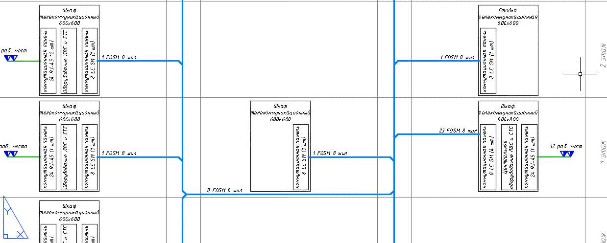
For the areas to be rented out, SCS is not provided. The main SCS cable system on the floors of the building intended for lease assumes the laying of a single-mode fiber-optic cable to each of the floors to enable unimpeded provision of the service delivery transport environment to the provider chosen by the tenant. For laying in the CC floors it is assumed to use a fiber-optic cable with a capacity of 8 wires.
2.1.4. Requirements to the backbone cable subsystem
SCS vertical cabling subsystem provides connection of the SCS to the SCS floor switching centers (SCs) by single-mode fiber-optic cable with 8 core capacity.
Vertical SCS cable subsystem is supposed to be laid in special dedicated cable channels (embedded pipes and cable trays).
The vertical cabling subsystem ensures data transmission at the speed of no less than 10 Gbit/s.
It is assumed that optical or copper (depending on the type of PBX selected at the detailed design stage) vertical communication lines connecting the GSC premises with the ATC equipment located in it (line crossing), and cross equipment of the floor distribution points will be arranged. For the telephone system of the building it is possible to use multipair cables of the 5th category as vertical cable lines.
2.1.5. Requirements for the horizontal cable subsystem
The horizontal SCS horizontal cabling subsystem provides the connection of terminal equipment of the various infrastructure systems of the Facility to the switching centers (CC) of the floors. Horizontal cabling subsystem is designed using twisted pair cable of category 6 or higher and provides for transmission of data along any path between equipment and network stations at a speed of at least 100 Mbit/s. At the workplaces of the personnel equipped with SCS is supposed to install a modular socket containing two RJ-45 ports for the connection of an automated workstation and telephone equipment. According to the requirements of ISO / IEC 11801 length of cables of horizontal subsystem from the server or from the cross cabinet to the workplace shall not exceed 90 meters.
Horizontal cabling subsystem SCS mounted in the corridors - in trays behind the false ceiling in the working and living space covertly - in plastic PVC pipes.
Horizontal cabling for the leased premises is not provided by this project and shall be performed by the tenants after the premises of the complex are put into operation.
2.1.6. Requirements for SCS switching centers
The SCS Communications Center provides for open two-frame 19" telecommunication racks for the installation of the patch panels, cable management and active equipment systems. The requirement for restricting unauthorized access in this case is achieved by locking and equipping the SCS room itself with access control system elements due to the small size of the room. Active equipment of the local area network (LAN), if necessary, will be located in the cabinets and racks of the SCS and floor SCS. In the room SCC expects to install standard enclosed telecommunication cabinets at least 800x800 42U or more in case the appropriate size of the switching space, providing installation of the required number of active and passive switching equipment will not provide a reserve of at least 25% of the calculated.
2.1.7. Requirements for workstation equipment
Socket blocks will be installed at the typical workplaces. Each block contains two RJ-45 sockets, one of which is designed to connect a personal computer, the second - to connect a telephone set. Cable separation schemes are unified and provide a guaranteed connection to the cable system of LAN equipment and telephone equipment (personal computers, network printers, servers, other computer equipment that has standard interfaces for connecting to local computer networks, as well as digital and analog telephones).
The project provides workstations for the following functional areas:
- Administrative hotel rooms: 1 workplace at 6 m.s.;
- Administrative rooms of operation service: 1 workplace for 8 sq.m;
- Administrative offices of the operation service: 1 work place per room; - Office space of the operation service: 1 work place per room: 1 workstation per room;
- Control room, central control room (each workplace);
- Technical rooms (where necessary): 1 workplace per room;
-Hotel room capacity: 2 workstations per room.
These instructions are preliminary, the exact number and location of workstations is made in accordance with the design project of a particular functional area.
2.2. Local computer network
The projected complex provides for the organization of a local computer network as part of the building's own needs. For the rented premises the LAN may be organized by the additional contract. The computer network is meant for processing and transferring information from all the departments and services of the complex, organizing the management system and Internet access. Computer equipment, software and network parameters are selected at the stage of detailed design.
For LAN used cable channels and rooms for installing equipment described in the section SCS.
The project provides for the possibility of wireless access to the local network and the Internet (WI-FI) at the request of the customer.
Standards for the LAN - Gigabit Ethernet - IEEE 802.3z (1000BaseSX, 1000BaseLX, 1000BaseCX), IEEE 802.3ab (1000BaseT) and IEEE 802.3u (100BaseTX). The topology is star. Active equipment is installed in the crossover rooms if necessary.
The local area network is based on a composite layered network model with the following functional modules:
- Core level;
- Access level;
- Server farm;
-Safety loop.
2.2.1. Core level, server farm, security loop.
The composition of equipment will be determined in the course of detailed design as specified by telecommunication service providers and customer requirements.
2.2.2. Access Layer.
Switches of access level are installed in the premises of communication centers (CC). Each access level switch has an optical channel with a bandwidth of no more than 10 Gbps to the core equipment. Each switch must have the number of copper ports with bandwidth of no more than 100/1000 Mbps with power supply (PoE) for connection of user equipment and Wi-Fi access points necessary for building functioning.
2.3. The telephone system
The telephone communication system is carried out for the building, the STS for the whole building is carried out under the additional contract.
The automatic telephone communication system is based on the digital automatic telephone exchange "Alcatel".
The architecture of the PBX assumes further development and increase in the number of telephone subscribers by installing additional media gateways or additional subscriber boards in the existing media gateways. In connection with this requirement, the architecture of the processor-gateway interaction over IP is used. The telephony control processor shall be selected during detailed design based on the maximum number of subscribers in the building.
The project provides for the possibility of organizing and using both IP telephony and analog phones.
2.3.1. Requirements for functional purpose
JTS provides:
-intra-office telephone, facsimile, and modem communication with a reduced numbering;
- access to city, long-distance and international lines;
- connection to existing telephone networks (if any);
- recording of telephone conversations;
- direct speakerphone communication "director-secretary".
2.3.2. Requirements to the PBX
The PBX has the following requirements:
- PBX must be of modular design and have a distributed architecture;
- PBX must meet the objectives of call holding, their acceptance and processing, forwarding (for busy, by "no answer"), the ability to organize pickup-groups and conference calls (the connection in a conversation with more than two subscribers), voice or unified mail, etc;
- PBX must have an integrated system of mini-cellular communication standard DECT with the possibility of further use at the request of the customer;
- PBX shall not require forced ventilation and cooling.
- PBX should work with different inter-station signaling systems without any changes in the configuration and composition of the equipment;
- PBX should provide directory service for storing information about system subscribers;
- PBX must provide the possibility of remote configuration and monitoring (using a secure protocol);
- PBX shall provide voice messaging functions and the possibility of various implementations of voice mail systems;
- Charging of all telephone conversations;
- Traffic accounting for incoming and outgoing calls;
-ATC must be provided with warranty and post-warranty service;
- ATC must have the minimum required amount of spare parts and accessories,
- ATC should have a certificate of the Ministry of Communications of Russia.
PBX equipment shall be installed in the HCC room meeting the requirements for the equipment rooms set forth in the relevant chapters of the TIA/EIA-568B standard.
More detailed requirements for the PBX will be defined and agreed with the Customer in the process of detailed system design.
2.4. System of urban radio broadcasting network
The multifunctional complex is equipped with means for receiving programs of the city radio broadcasting network.
The broadcasting network of the building is intended for the reception of signals from the Moscow City Radio Broadcasting Network (MGRS) and the broadcasting of the 3 program wired radio broadcasts and programs of the Civil Defense and Emergency situations in the service rooms, hotel rooms (apartments).
The following equipment will be used for the site's radio broadcasting network: a TGA-10 subscriber transformer (or some more, depending on the number of subscribers), a rack for the lines of the wired broadcasting network, a distribution and limiting box, a radio socket for the wired broadcasting network, a subscriber loudspeaker. The equipment type shall be selected in accordance with the MGRS specifications.
The indoor radio broadcasting network is performed from the subscriber's transformer with the installation of limiting boxes in the floor communication cabinets and sockets. Radio broadcasting network outlets shall be installed, in rooms with personnel on duty 24 hours a day:
- in the premises of the security services (CPO SPS and SB);
-control room of engineering systems.
For the apartments, the number of distribution boxes required to connect the MGRS points, based on one radio point in the administration premises, on-duty personnel, and the apartment. The number of radio points will be specified in the working design.
In the premises of control rooms and security services are provided 3 program loudspeakers, which through radio sockets are connected to the radio distribution network. Power supply of radio receivers is carried out from AC 220V, and, to ensure the possibility of connecting 3 programmable speakers, power outlets 220V installed at a distance of not more than 1.0 m from the radio sockets.
Signals MGRS connected to the equipment warning and evacuation management system (SOUE) to organize the translation of signals MGRS in a fire. Thus, the fire alarm and evacuation control system issues messages to all the premises of the complex with permanent or temporary occupancy. For the transmission of MES messages about emergencies, the signal from the distribution radio broadcasting network is fed to the input of the fire alarm control system.
For the building, the signal input of the MGRS is carried out according to the technical specifications received by FSUE MGRS (according to the external network project).
The radio system cable shall be laid in low current risers, ducts and PVC pipes.
2.5. System clock system.
The created clock system is an integral part of the general facility control system and is designed to synchronize the exact time of the dispatching systems, security systems, local computer network using the radio signal from the GPS system.
The clock system consists of:
- A single microprocessor-based clock station;
- Radio time correction module by GPS signal with an antenna;
-secondary clock and scoreboard (with date and time display);
- distribution network.
Preliminarily as a secondary clock should be selected devices with a diameter of 40 cm, scoreboard with a height of signs not less than 100 mm.
Clocks and displays are proposed to be installed in all elevator lobbies, reception areas, lobbies. The exact places of installation are determined at the working design stage and coordinated with the developers of the design project.
The clock microprocessor station is automatically synchronized with the help of radio corrections device which consists of GPS signal receiver with an external active antenna.
The active antenna is installed in the area of a confident GPS signal reception. The exact location of the antenna is selected during the detailed design phase.
Cables are wired with cables recommended by manufacturers of equipment. Predominantly non-combustible cables with low smoke emission are used.
Cables are laid in trunk conduits of the facility on trays and in ducts, as well as in PVC pipes.
Earthing and grounding of electrical consumers shall be performed in accordance with Electrical Installation Regulations.
Power supply of the system shall be performed according to the 1st category of reliability.
2.6. Cable TV system
Cable TV system provides:
- The ability to broadcast over a distribution network a set of channels of cable broadcasting television;
-reception and broadcasting of satellite broadcast television signals for the hotel.
The number and composition of satellite broadcasting channels is determined at the stage of detailed design and agreed with the Customer. The number and composition of cable broadcasting channels shall be determined by the cable TV service provider and the Customer.
2.6.1. Distribution of TV signal
Distribution network is designed to work in the range of 950-2400 MHz (satellite broadcasting in the hotel), 47 - 862 MHz (cable broadcasting). Distribution network equipment includes: amplifiers, switches SAT (multiswitches), dividers, taps.
TV socket is provided in the room of the central control panel for security systems and fire protection systems.
For the rented premises, the installation of outlets is not provided, and the taps are installed on the following calculation:
- for offices 4 taps per floor;
- for the hotel, one outlet per apartment;
- for the restaurant - 4 outlets;
All active amplifying equipment and passive equipment of the distribution network shall be installed in the floor distribution cabinets. To supply power to the active equipment, each cabinet is equipped with 2P+N standard sockets. Cable routes are laid together with cable routes of low-voltage systems. Grounding and grounding of electrical consumers is performed in accordance with the requirements of Electrical Installation Regulations. Power supply of the system is carried out according to the 1st category of reliability.
2.7. Selector communication system (SCS) with the security zones of the MMGN.
The selector communications system (SCS) with MSHI (low-mobile population groups) safety zones includes:
- two-way loudspeaker communication of the dispatcher of the Central Dispatcher Service and SPZ (room 01-84 - 1st floor) with the security zones of persons with low mobility (in accordance with SP 59.13330.2012)
- two-way loud-speaking communication of the dispatcher with the elevator lobbies, where the presence of MSGBIs is possible.
At this facility, the safety zones, in accordance with the Measures to ensure access for persons with disabilities (ODI), are the elevator halls on the 1st and (-1) floors. In accordance with the ODI, only elevator halls where MSGBIs may be present are equipped with conference calls. At the facility for the organization of intercom system proposed to install IP-intercom on the basis of a switchboard N-8000EX firm "TOA". Switches selector communications system installed in a 19 "racks, cabinets on the floors, together with the equipment IMS and connected to the network switch in a 19 "rack in the CPU SB and SPZ (Room 01-84 - floor 1). Each N-8000EX switch has the ability to connect up to 16 N-8050DS door stations. Door stations (intercom) are installed in elevator lobbies and security areas.
For communication with the alarm zones in the control center of the SB and SPZ is installed multifunctional master station system IP-intercom N-8000MS.
Cable lines of the system are made with fire-resistant cables.
In terms of power supply reliability, electrical consumers of the subsystem belong to the 1st category according to Electrical Installation Regulations.
The organization of the selector communication system is shown in the structural diagram. The location of the door stations is shown on the equipment layout plans.